Multifunctional physiotherapy instrument

A multi-functional and instrumental technology, applied in physical therapy, passive exercise equipment, medical science, etc., can solve the problems of complex transmission structure of electronic drive components, cumbersome structural design, high production cost, and reduce production costs and post-maintenance. Difficulty, improve market competitiveness, and use flexible and convenient effects

Inactive Publication Date: 2020-09-15
吕文先
View PDF9 Cites 0 Cited by
  • Summary
  • Abstract
  • Description
  • Claims
  • Application Information

AI Technical Summary

Problems solved by technology

[0002] Physiotherapy is a common method for treating spondylosis. A variety of physical therapy devices have been developed for spondylosis technicians. These physical therapy devices can be roughly divided into two types: manual operation and automatic control; among them, the manually operated physical therapy device is manually inflated. Or manually adjust the height of the noose to achieve cervical traction physiotherapy, but no matter whether it is manual inflation or manual adjustment of the height of the noose, the user needs to repeatedly operate, which is very troublesome to use; although automatic control is fast and convenient, the existing automation The structural design of the cervical physiotherapy device is relatively cumbersome, the electronic drive components and transmission structure used are relatively complicated, the production cost is high, and the later maintenance is difficult

Method used


Image

  • Multifunctional physiotherapy instrument
  • Multifunctional physiotherapy instrument
  • Multifunctional physiotherapy instrument

Examples


Embodiment Construction

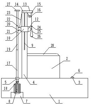
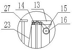
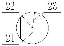
[0027] The present invention is specifically described below in conjunction with accompanying drawing, as Figure 1-5 shown;

[0028] The invention point of the present application is that square stool 2, pedal 3, column 4 and bearing 5 are fixedly installed on the base, the pedal is positioned at one side of the square stool, and two foot switches 6 are installed on the pedal, and the bearing Located on the other side of the square stool, the column is located between the square stool and the bearing, the motor mount 7 is fixedly installed inside the base, the motor mount is located directly below the bearing, and the servo motor is fixedly installed on the motor mount The motor 8 and the two foot switches are respectively connected to the control part of the servo motor, and the two foot switches control the forward and reverse rotation of the servo motor through the control part of the servo motor.

[0029] The invention of the present application is also that the column i...


PUM


Abstract

The invention discloses a multifunctional physiotherapy instrument. The multifunctional physiotherapy instrument comprises a base, wherein a square stool, a pedal, an upright post and a bearing are fixedly installed on the base; the pedal is located on one side of the square stool, two foot switches are installed on the pedal, the bearing is located on the other side of the square stool, and the upright post is located between the square stool and the bearing; a motor installation seat is fixedly installed in the base, and is located below the bearing; a servo motor is fixedly installed on themotor installation seat; the two foot switches are connected with the control part of the servo motor, and control the servo motor to rotate forward and turn over through the control part of the servo motor; the upright post is next to the square stool; the upright post is a square upright post; and a sliding groove is formed in the side surface of the upright post and located at the upper part of the upright post. The multifunctional physiotherapy instrument has the beneficial effects of being convenient to operate and high in practicability.

Description

technical field [0001] The invention relates to the technical field of structural improvement of physical therapy devices, in particular to a multifunctional physical therapy device. Background technique [0002] Physiotherapy is a common method for treating spondylosis. A variety of physical therapy devices have been developed for spondylosis technicians. These physical therapy devices can be roughly divided into two types: manual operation and automatic control; among them, the manually operated physical therapy device is manually inflated. Or manually adjust the height of the noose to achieve cervical traction physiotherapy, but no matter whether it is manual inflation or manual adjustment of the height of the noose, the user needs to repeatedly operate, which is very troublesome to use; although automatic control is fast and convenient, the existing automation The structural design of the cervical spine physiotherapy device is relatively cumbersome, the electronic drive ...

Claims


Application Information

Patent Timeline
Patent Type & Authority Applications(China)
IPC IPC(8): A61F5/042A61H1/02
CPCA61F5/042A61H1/0222A61H1/0296A61H2201/0192A61H2201/1207A61H2201/1633A61H2201/1607A61H2201/5023A61H2205/04
Inventor 吕文先
Owner 吕文先
Why Eureka
Try Eureka