

Exercise device for arm rehabilitation
An exercise device and arm technology, which is applied to massage auxiliary products, physical therapy, gymnastics equipment, etc., can solve the problems of boring exercise and single function, and achieve the effects of good rehabilitation training, good service and strong practicability.
- Summary
- Abstract
- Description
- Claims
- Application Information
AI Technical Summary
Problems solved by technology
Method used
Image

Examples
Embodiment 1
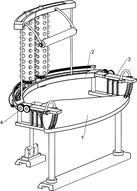
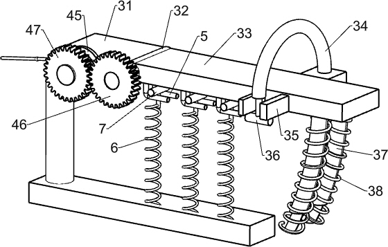
[0021] An exercise device for arm rehabilitation, such as Figure 1-4 As shown, it includes a bracket 1, a back massage component 2, an arm exercise component 3 and a connection component 4. The left side of the top of the bracket 1 is provided with a back massage component 2 that massages the back by rotating, and the front and rear sides of the top of the bracket 1 are installed There is an arm exercising assembly 3 for exercising the arms by rotating, and a connecting assembly 4 is arranged between the arm exercising assembly 3 and the back massage assembly 2 .
[0022] When needing to use this device to carry out the exercise rehabilitation of arm, first people sit on support 1, arm is placed on arm exercise assembly 3, back leans on back massage assembly 2, at this moment, begin to exercise people by arm exercise assembly 3 arm, the arm exercising component 3 drives the back massaging component 2 to start working through the connecting component 4, and massages the back o...
Embodiment 2
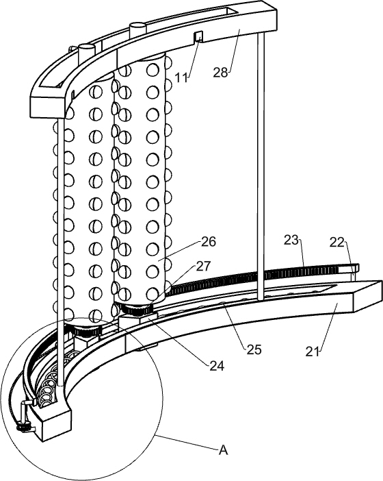
[0024] On the basis of Example 1, such as Figure 1-5 As shown, the back massage assembly 2 includes a lower track 21, a pole 22, an arc rack 23, a slider 24, a first spring 25, a massage wheel 26, a first gear 27 and an upper track 28, and the left side of the top of the support 1 passes through the The bolts are fixedly connected with a lower track 21, three struts 22 are welded on the left side of the lower track 21, arc-shaped racks 23 are welded between the tops of the struts 22, and sliders 24 are slidingly arranged on the front and rear sides of the lower track 21. A first spring 25 is connected between the slider 24 and the lower track 21, and the top of the slider 24 is rotatably provided with a massage wheel 26, and the bottom of the massage wheel 26 is connected with a first gear 27, and the first gear 27 is connected to the curved rack. 23 engaged, the top of the lower track 21 is fixedly connected with the upper track 28 by bolts, and the upper track 28 is slidabl...
PUM
 Abstract
Description
Claims
Application Information