


Quick Research
Generate reliable direction feasibility study reports for your R&D in just a few steps.

Technical Q&A
Discover and master advanced knowledge NOW. Basics, ideas, possibilities, all at once.

Find Solutions
As an expert in R&D theories, this can generate solutions to your technical problems instantly.

Evaluate Feasibility
Analyze your overall solution with one click, know your potential R&D risks in advance.

Monitor Landscape
Get weekly tech updates, stay abreast of the latest tech innovations and key insights.
Floating pressing mechanism and using method thereof
A floating pressing and floating mechanism technology, applied in workpiece clamping devices, manufacturing tools, etc., can solve the problem of no pressing mechanism, avoid gross errors, and meet the requirements of rotary follow-up and adjustable pressure.
- Summary
- Abstract
- Description
- Claims
- Application Information
AI Technical Summary
Problems solved by technology
Method used
Image

Examples
Embodiment 1
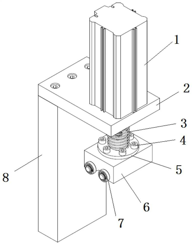
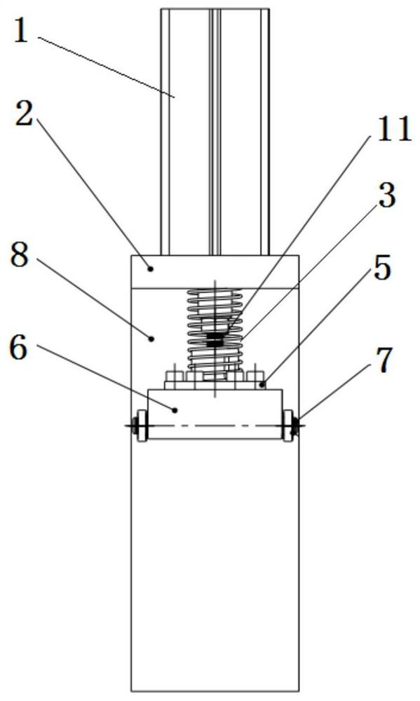
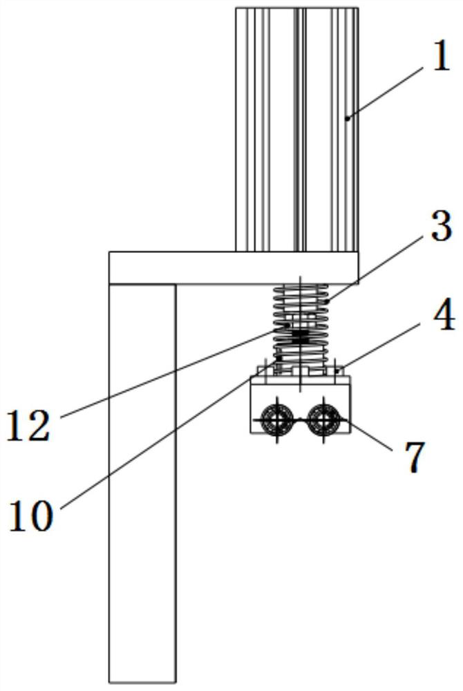
[0038] A floating pressing mechanism in this embodiment includes a support frame for supporting the whole mechanism. The upper and lower end surfaces of the support frame are horizontal planes parallel to each other, and the upper end is provided with a convex edge extending to one side. A cylinder is provided, the cylinder rod of the cylinder is vertically downward, the bottom end of the cylinder rod is detachably connected with a vertical connecting rod, and a connecting sleeve is slidably connected to the bottom end of the connecting rod, and a connecting sleeve is provided outside the connecting sleeve. Compression spring, the compression spring is sleeved outside the connecting rod and its inner ring is in clearance fit with the outer ring of the connecting sleeve. The bottom end of the connecting sleeve is fixedly connected with a compression block, and the four can rotate freely. The pressing wheels are symmetrically arranged on the left and right sides of the bottom sur...
Embodiment 2
[0043] On the basis of the first embodiment above, as a preference, the specific structure of the support frame is: including a vertical plate and a cylinder seat plate, the vertical plate is vertically arranged, and the parallelism between the bottom surface and the top surface is required to be 0.01mm, And its bottom surface and top surface are provided with connecting screw holes; the cylinder seat plate is used to carry the cylinder, and is horizontally arranged on the top surface of the vertical plate, and one end of the top surface of the cylinder seat plate near the edge is opened for Through hole through the cylinder rod.
[0044] Preferably, the connecting rod is a threaded rod, and one end connected to the cylinder is locked by a nut to limit the axial direction, and the other end is provided with a through hole in the radial direction for passing through the limit pin. The shape of the longitudinal section of the hole is a circle with the same diameter as the width ...
Embodiment 3
[0049] On the basis of the second embodiment above, as a preference, the specific structure of the connecting sleeve is a flange structure, the small-diameter section of the flange faces upward, and strip-shaped passages are symmetrically opened along the radial direction of the small-diameter section. hole, and the small-diameter section is a hollow tubular structure, the two ends of the limit pin are located in the strip-shaped through-hole and can freely slide up and down in the strip-shaped through-hole without falling off; There is a stepped through hole in the center of the large diameter section of the flange, which can pass through the connecting screw and limit the axial direction. There is an annular array of through holes around the stepped through hole, which is used to pass the fastener to connect the connecting sleeve to the described The compression block secures the connection.
[0050] As a preference, a V-shaped groove is opened in the center of the bottom su...
PUM
 Abstract
Description
Claims
Application Information
 - R&D Engineer
- R&D Manager
- IP Professional
- Industry Leading Data Capabilities
- Powerful AI technology
- Patent DNA Extraction
Browse by: Latest US Patents, China's latest patents, Technical Efficacy Thesaurus, Application Domain, Technology Topic, Popular Technical Reports.
© 2024 PatSnap. All rights reserved.Legal|Privacy policy|Modern Slavery Act Transparency Statement|Sitemap|About US| Contact US: help@patsnap.com