Eureka AIR delivers breakthrough ideas for toughest innovation challenges, trusted by R&D personnel around the world.

Mechanical pressure apparatus of sintering furnace

A mechanical pressure, sintering furnace technology, applied in the field of pressure devices, can solve the problems of difficult maintenance, difficult unbalanced pressure, complex structure, etc., and achieve the effects of easy assembly and disassembly, convenient pressure adjustment, and large adjustment range.

Inactive Publication Date: 2010-09-29
SICHUAN NORMAL UNIV
View PDF5 Cites 0 Cited by
  • Summary
  • Abstract
  • Description
  • Claims
  • Application Information

AI Technical Summary

Problems solved by technology

Existing pressure devices or pressurizing devices are generally hydraulic structures, and the pressure head is controlled by the hydraulic system and provides pressure (for example: the pressure device in the "hot-pressed sintering furnace with gas protection" with the announcement number CN2386409, the approval number is The pressure device in the "vertical pressurized continuous sintering furnace" of CN1019173, and the pressurization device in the "vacuum-hot-pressed sintering furnace" of CN1825041), and the hydraulic pressure device is not only relatively complicated in structure, but also has high cost and is not easy Maintenance requires power consumption, and it is not convenient to set up multiple sets on one sintering furnace, and it is difficult to implement unbalanced pressure on the sintered sample

Method used


Image

  • Mechanical pressure apparatus of sintering furnace
  • Mechanical pressure apparatus of sintering furnace
  • Mechanical pressure apparatus of sintering furnace

Examples


Embodiment 1

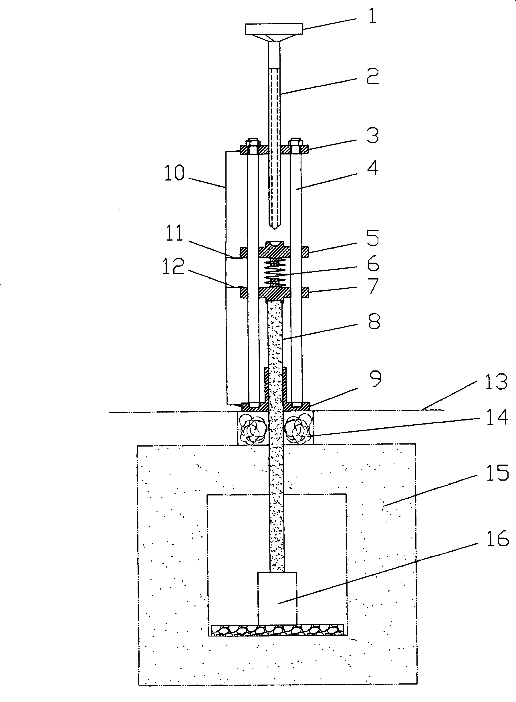
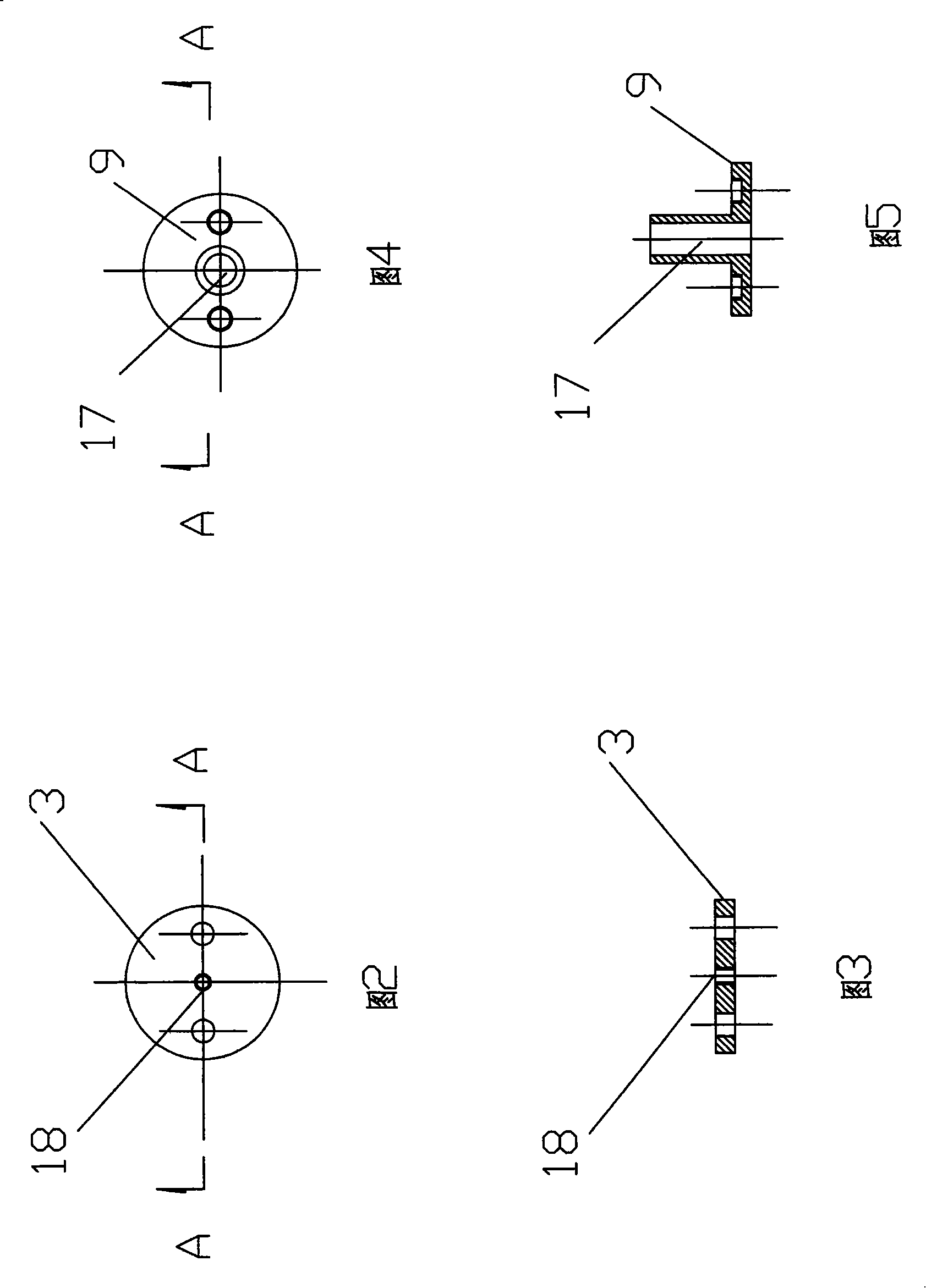
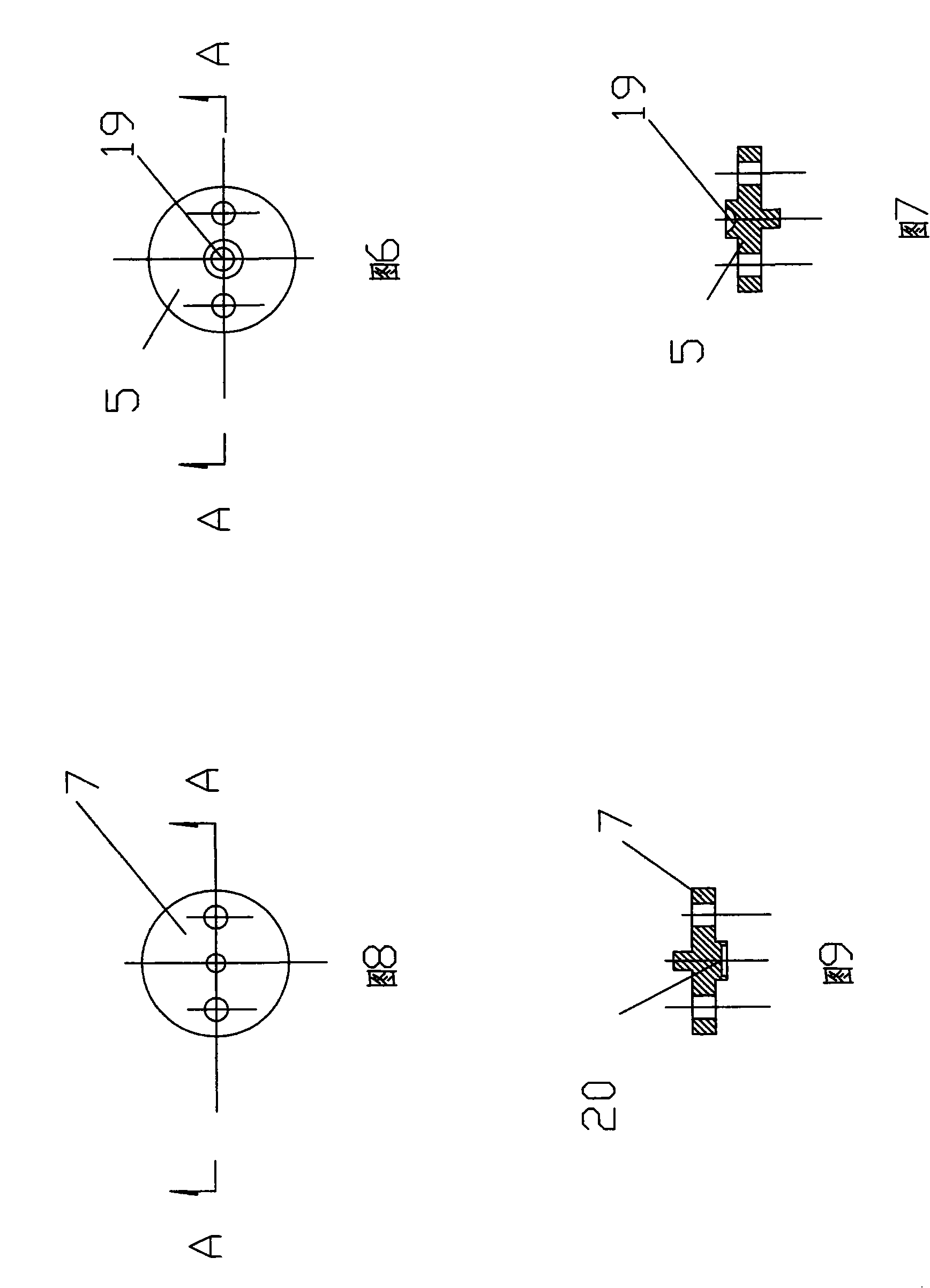
[0036] In this embodiment, the structure of the mechanical pressure device of the sintering furnace is as follows: figure 1 shown. The indenter 8 is a cylindrical indenter made of ceramic material. The support and guide mechanism includes a base 9, a guide column 4 and a cover plate 3; the shape and structure of the base 9 are as follows: Figure 4 , Figure 5 As shown, it consists of a circular chassis and a cylindrical boss located in the center of the chassis. The two are integrated structures. The center of the base is provided with a guide hole 17 that matches the indenter; the cover plate 3 is disc-shaped, such as figure 2 , image 3 As shown, the central part is provided with a screw hole 18; the guide column 4 is two, and its shape is cylindrical; the assembly method is: the center line of the cover plate 3 and the base 9 coincides, and the guide column 4 is symmetrical to the cover plate and the base. The center line is installed, and one end thereof is threadedl...

Embodiment 2

[0038] In this embodiment, six sets of mechanical pressure devices with structures as described in Embodiment 1 are installed on the atmosphere sintering furnace, and the installation method is as follows: Figure 11 , Figure 12 As shown, the base 9 is installed on the furnace body shell 13 of the atmosphere sintering furnace, surrounding the indenter 8, and an insulating sealing sleeve 14 is arranged between the furnace body shell 13 and the furnace body 15; six samples are placed in the hearth of the atmosphere sintering furnace .

[0039] Before use, first use the pressure sensor (electronic scale, the unit is kg, 1 decimal place) to check the selected six sets of force transmission springs respectively, and draw the "scale-quality" diagram of each force transmission spring.

[0040]When drawing the "scale-mass" diagram of each force transmission spring, the following points should generally be selected (the "scale-mass" diagram should be a straight line according to Hook...


PUM


Abstract

The invention relates to a mechanical pressure device applied to a common or low-pressure atmosphere sintering furnace, which comprises a pressing head, a support and guide mechanism, a mechanical pressure mechanism, a mechanical power-transmission mechanism, and a pressure detection mechanism. The mechanical pressure mechanism comprises a screw and an energizing pan which is arranged at the upper end of the screw, the mechanical power-transmission mechanism comprises an upper slip pan, a lower slip pan, and a power-transmission spring, the pressure detection mechanism comprises a scale and apointer. The assembly way is that the mechanical pressure mechanism and the mechanical power-transmission mechanism are arranged on the support and guide mechanism; the scale is arranged on the support and guide mechanism, the pointer is arranged on the mechanical power-transmission mechanism; the pressing head is inserted and arranged in the guide hole arranged at the support and guide mechanism, when the pressing head works, the upper end of the pressing head contacts with the mechanical power-transmission mechanism, the lower end of the pressing head contacts with the sintered sample in the sintering furnace. The mechanical pressure device not only has the advantages that the structure is simple, and the cost is low; but a plurality of mechanical pressure devices can be arranged on onesintering furnace, thereby pressuring a plurality of sintered samples or applying non-equilibrium pressure on one sintered sample.

Description

technical field [0001] The invention belongs to a pressure device (also known as a pressure device) for a sintering furnace, in particular to a mechanical pressure device for an ordinary sintering furnace and a general atmosphere sintering furnace. Background technique [0002] When materials or finished products are prepared by sintering under pressure, the density of materials and samples can be increased, various voids can be reduced, especially for the formation of excellent heterogeneous interface structures, and the function of sample devices can be improved. important role. Among them, the pressure device or pressurization device matched with the sintering furnace is an indispensable equipment. Existing pressure devices or pressurizing devices are generally hydraulic structures, and the pressure head is controlled by the hydraulic system and provides pressure (for example: the pressure device in the "hot-pressed sintering furnace with gas protection" with the announc...

Claims


Application Information

Patent Timeline
Patent Type & Authority Patents(China)
IPC IPC(8): B30B1/00F27B5/00
Inventor 杨春余毅代辛张万里张毅
Owner SICHUAN NORMAL UNIV
Why Eureka
Eureka Blog
Learn More