Adsorption buffer device

A buffer device and driven shaft technology, which is applied in the direction of transportation and packaging, chucks, conveyors, etc., can solve the problem of increasing the pushing force of the object to be transferred, and achieve the effect of stable adsorption

Active Publication Date: 2020-09-15
CKD
View PDF8 Cites 1 Cited by
  • Summary
  • Abstract
  • Description
  • Claims
  • Application Information

AI Technical Summary

Problems solved by technology

In addition, when the suction part is pushed against the object to be transferred, in order to buffer the push reaction force, the driven shaft needs to be moved in the axial direction, but additional pressure for connecting the driven shaft to the movable shaft must be applied. The force that pulls the end away from the end of the seal member facing the driven shaft increases the pushing force acting on the object to be transferred

Method used


Image

  • Adsorption buffer device
  • Adsorption buffer device
  • Adsorption buffer device

Examples


Embodiment Construction

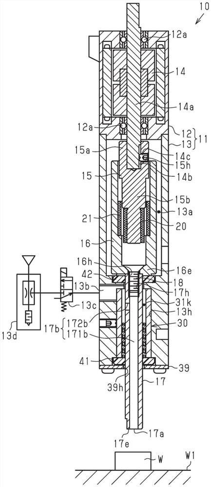
[0024] Below, according to Figure 1 to Figure 3(b) An embodiment in which the adsorption buffer device is embodied will be described. The suction buffer device according to the present embodiment suctions transfer objects such as electronic components. Furthermore, figure 1 In , the lower side is defined as the front end side of the suction cushioning device, and the upper side is defined as the base end side of the suction cushioning device.

[0025] Such as figure 1 As shown, the housing 11 of the suction buffer device 10 has a motor housing 12 and a cylindrical body housing 13 connected to the motor housing 12 . Inside the motor housing 12, a rotor 14 having a rotating shaft 14a is provided therein. The main body case 13 is connected to the motor case 12 such that the axial direction of the main body case 13 coincides with the axial direction of the rotation shaft 14a.

[0026] The rotary shaft 14a is rotatably supported by the motor case 12 via a bearing 12a. Both e...


PUM


Abstract

An adsorption buffer device includes a housing, a drive shaft, a driven shaft, magnets, and a sealing member. The opposing surfaces of the magnets are magnetized with different magnetic poles, so thatthe magnets are non-contact and deviate the overlap of the axial magnetic poles. While the attractive force in the axial direction to be restored acts on a movable shaft, the movable shaft moves. Thefront end portion of the driven shaft adjacent to the movable shaft and the base end portion of the sealing member opposed to the driven shaft can be abutted against each other. At least any one of the front end portion of the driven shaft and the base end portion of the sealing member opposed to the driven shaft is provided with a connecting passage that communicates the outer periphery and theinner periphery of the side opposed to the driven shaft of the sealing member.

Description

technical field [0001] The present invention relates to an adsorption cushioning device for adsorbing an object to be transferred such as an electronic component. Background technique [0002] In general, an actuator is attached to a suction buffer device that suctions a transfer object such as an electronic component. The adsorption cushioning device has an adsorption unit that adsorbs the object to be transferred. Then, when the object to be transferred is sucked by the suction part, the actuator is driven to move the suction buffer device toward the object to be transferred, and the suction part is pressed against the object to be transferred. At this time, if the pushing force acting on the object to be transferred is too large, excessive pressure may act on the object to be transferred. However, if the pressing force acting on the object to be transferred is too small, the object to be transferred may not be adsorbed by the adsorption unit. [0003] Therefore, for ex...

Claims


Application Information

Patent Timeline
Patent Type & Authority Applications(China)
IPC IPC(8): B25J15/06H05K13/04
CPCB25J15/0633H05K13/0409B65G47/91B25J15/0616F16J15/16H01F7/0252B65G2201/02F16C2326/58
Inventor 松永晴广伊藤秀和林本茂伊藤正齐
Owner CKD
Why Eureka
Try Eureka