Controlling method and apparatus for feeding motor transfer of optical record player

A technology of feed motor and control method, which is applied in magnetic recording, data recording, recording information storage, etc., can solve problems such as spinning, interference, and optical pickup cannot move, and achieve stable feed transfer, stable tracking track, Reduce the effect of joint properties

Inactive Publication Date: 2005-02-23
LEJIN GUANGDIAN ELECTRONIC CO LTD SHANGHAI
View PDF0 Cites 0 Cited by
  • Summary
  • Abstract
  • Description
  • Claims
  • Application Information

AI Technical Summary

Problems solved by technology

[0016] At this time, the feed and transfer servo driver 104 also occurs due to defects or disturbances. In the opposite direction of the feed and transfer direction, for example, the phenomenon of slipping

Method used


Image

  • Controlling method and apparatus for feeding motor transfer of optical record player
  • Controlling method and apparatus for feeding motor transfer of optical record player
  • Controlling method and apparatus for feeding motor transfer of optical record player

Examples


Example Embodiment

[0052] Hereinafter, with reference to the embodiments of the drawings, the embodiments of the method and device for controlling the feeding of the feed motor of the optical recording player of the present invention will be described in detail.

[0053] The structure and function of the present invention are illustrated by one embodiment. The structure and function of the present invention as described above are not limited to the one embodiment cited here.

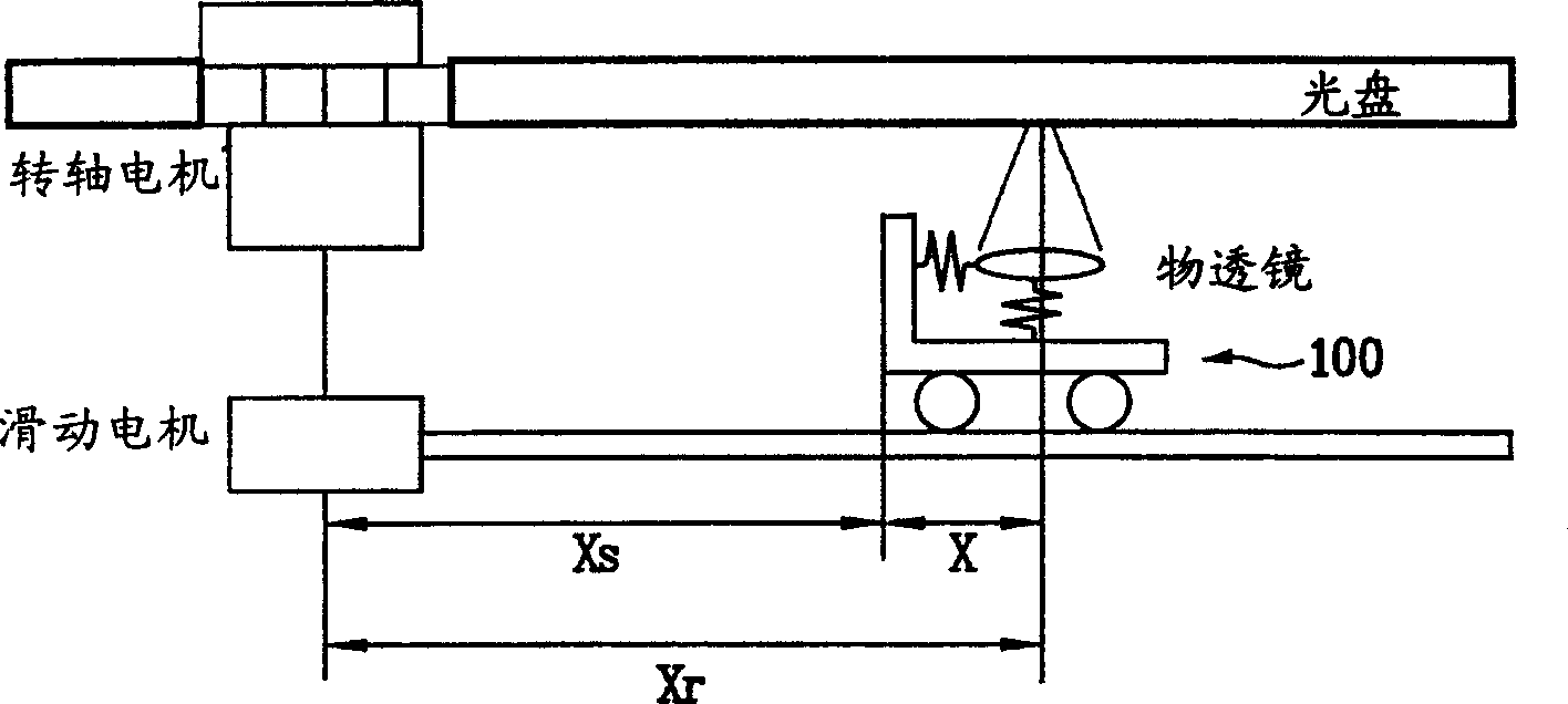
[0054] The present invention utilizes the optical disc rotation information, after the feed motor is transferred to the track pitch every one revolution, the existing feed transfer servo drive unit and tracking servo drive unit are used to control residual errors that occur thereafter.

[0055] Here, the track pitch differs depending on the type of optical disc. The DVD series is 0.74um, and the CD is 1.6um.

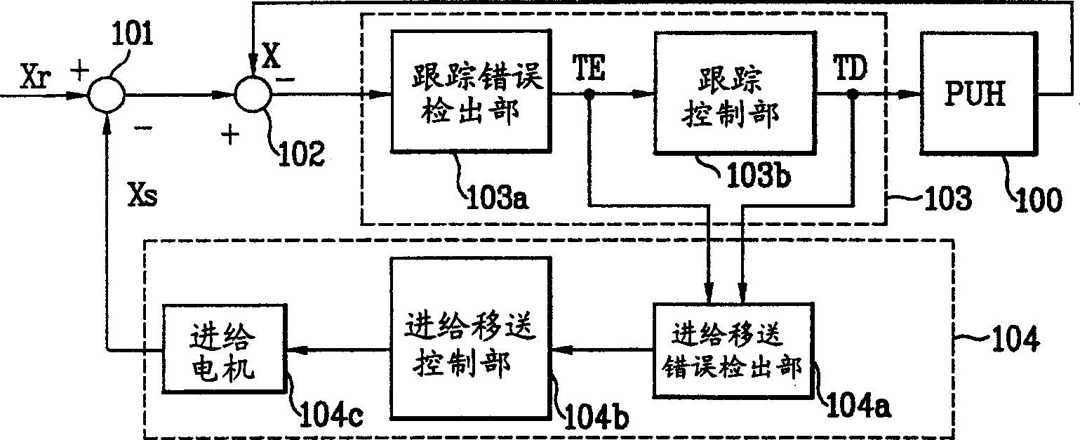
[0056] Figure 4 It is a structural diagram of the optical disc drive system according to the present invention. in F...


PUM


Abstract

In this apparatus, every circle the CD rotates, the optical collector will move on the track with configured distance. Through the remained error on existed tracking driver, the dependence on the moving driver is minimized to compensate the remained error after the movement of the rotating information. Thus the moving error is rapidly compensated, and the remained error is minimized.

Description

(1) Technical field [0001] The present invention relates to the control method and device for the transfer of the feed motor of the optical record player, in particular to a feed transfer control method for a certain amount of feed transfer for an optical record player whose result is fed back and used for feed transfer control. A control method and device for motor transfer. (2) Background technology [0002] Generally, in the standard servo, only the tracking servo is used, and when the optical pickup tracks the eccentricity of the optical disc, due to the limitation of the drive range of the tracker, there will be a feeding error that the actuator does not track. Such infeed errors need to be tracked by the infeed drive. [0003] figure 1 is a schematic diagram of an ordinary CD-ROM drive system, figure 2 It is a structural diagram of the above-mentioned optical disk drive system. [0004] That is, in order to rotate the optical disk, the spindle motor generates rota...

Claims


Application Information

Patent Timeline
IPC IPC(8): G11B7/09G11B19/247G11B19/28
Inventor 金京洙朴相温
Owner LEJIN GUANGDIAN ELECTRONIC CO LTD SHANGHAI
Why Eureka
Try Eureka