Vehicle and brake torque control method thereof

A technology of vehicle braking and torque control, which is applied in the direction of control drive, control device, vehicle components, etc., can solve problems such as poor stability, and achieve the effects of strong applicability, easy promotion, and improved ride comfort

Inactive Publication Date: 2020-09-15
ZHENGZHOU YUTONG BUS CO LTD
View PDF8 Cites 4 Cited by
  • Summary
  • Abstract
  • Description
  • Claims
  • Application Information

AI Technical Summary

Problems solved by technology

[0004] The purpose of the present invention is to provide a vehicle braking torque control method to solve the problem that the existing control method adopts the same braking control strategy under the turning condition and the straight working condition, which leads to the poor stability of the vehicle when turning; A vehicle is provided to solve the problem of poor stability of the vehicle when turning due to the use of the same braking control strategy in the turning and straight-line conditions of the existing vehicles

Method used


Image

  • Vehicle and brake torque control method thereof
  • Vehicle and brake torque control method thereof
  • Vehicle and brake torque control method thereof

Examples


Embodiment 1

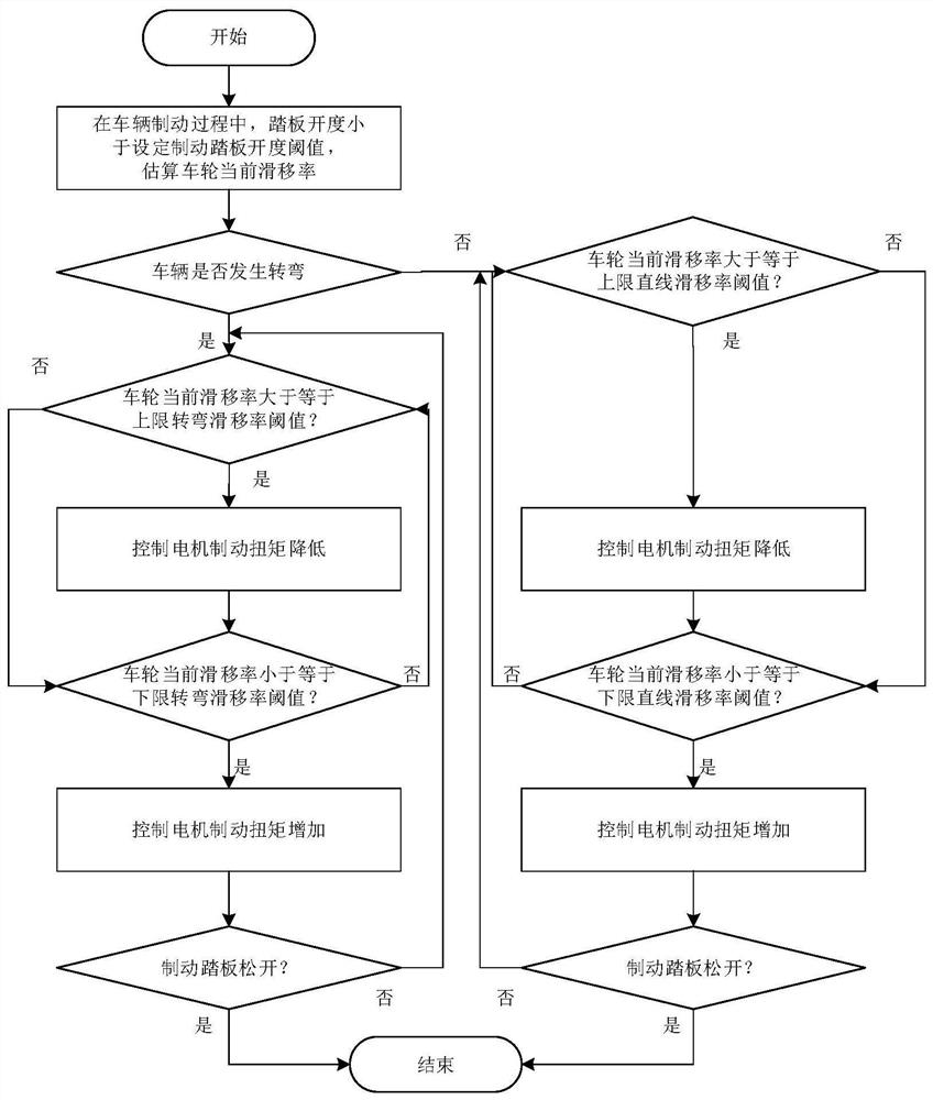
[0029] The vehicle braking torque control method proposed in this embodiment is as follows: figure 1 shown, including the following steps:

[0030] 1) During the vehicle braking process, it is judged whether the brake pedal opening (ie Brk) is greater than or equal to the set brake pedal opening threshold (ie Brk set ), if Brkset , obtain the steering wheel angle signal, wheel speed, wheel rolling radius and wheel center speed in real time, and estimate the current slip rate of the wheel according to the obtained wheel speed, wheel rolling radius and wheel center speed;

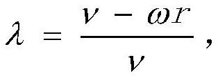
[0031] The formula for calculating λ of the current wheel slip ratio is:

[0032] The wheel center speed ν is:

[0033] The vehicle longitudinal speed V is:

[0034] where r l ,r r are the radii of left and right driven wheels respectively, w l ,w r are the wheel speeds of the left and right driven wheels, δ is the wheel angle, b is the wheel base (the track of the left and right symmetrical whee...

Embodiment 2

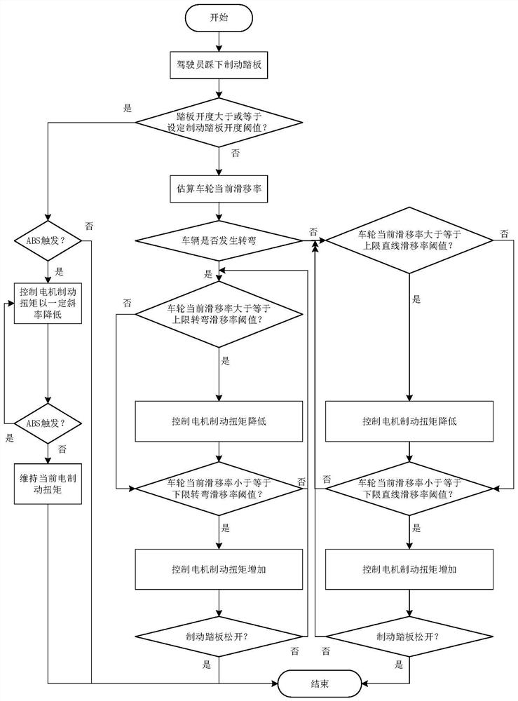
[0044] The difference between the vehicle braking torque control method proposed in this embodiment and the first embodiment of the vehicle braking torque control method is that during the vehicle braking process, the brake pedal opening (namely Brk) is increased to be greater than or equal to the set Brake pedal opening threshold (ie Brk set ) vehicle braking torque control method.

[0045] Specific steps such as figure 2 Shown:

[0046] 1) During the vehicle braking process, judge whether the brake pedal opening is greater than or equal to the set brake pedal opening threshold, if Brkset , obtain the steering wheel angle signal, wheel speed, wheel rolling radius and wheel center speed in real time, estimate the current slip rate of the wheel according to the obtained wheel speed, wheel rolling radius and wheel center speed; judge whether the vehicle is take a turn;

[0047] 2) If a turn occurs, judge whether the current slip rate of the wheel is greater than or equal to ...


PUM


Abstract

The invention relates to a vehicle and a brake torque control method thereof. The method comprises the following steps that: in a vehicle braking process, if the brake pedal opening degree is smallerthan a set brake pedal opening degree threshold value, the current slip rate of a wheel is estimated according to the speed, rolling radius and wheel center speed of a wheel; whether a vehicle turns or not is judged according to a steering wheel angle signal; if turning occurs, a wheel slip rate is controlled within a first slip rate interval; and if not, the wheel slip rate is controlled within asecond slip rate interval. According to the method, braking torque control is started in advance compared with linear driving during turning driving, so that the braking torque control opportunitiesof the vehicle under a turning working condition and a linear working condition are different, the braking stability and smoothness of the vehicle under the turning working condition are improved, andthe applicability of the vehicle is improved.

Description

technical field [0001] The invention relates to a vehicle and a braking torque control method thereof. Background technique [0002] At present, most of the new energy vehicles adopt the following braking methods: the brake pedal opening only adopts the electric braking method before the idling stroke, and there are both electric braking and mechanical braking methods after the idling stroke. Make full use of regenerative braking to improve economy and low cost. In order to prevent the vehicle from skidding due to wheel locking during the braking process, the electric brake needs to be removed when the anti-lock braking (ABS) signal is triggered (that is, when the wheels are locked). [0003] At this stage, there are two main control schemes for solving electric braking (ie regenerative braking) when ABS is triggered: 1. Electric braking is removed when ABS is triggered. Delay, when electric braking is dominant on low-attached roads, it will cause the wheels to lock and tr...

Claims


Application Information

Patent Timeline
Patent Type & Authority Applications(China)
IPC IPC(8): B60W30/18B60W50/00B60L15/20
CPCB60L15/2009B60L2240/423B60W30/18127B60W50/00B60W2050/0019B60W2520/00B60W2520/28B60W2710/083Y02T10/72
Inventor 郭潇然何亮石冠男卢甲华贾莉
Owner ZHENGZHOU YUTONG BUS CO LTD
Why Eureka
Try Eureka