Inner gear ring rod spacing detection tool and use method thereof

A technology of rod spacing and inner gear ring, which is applied to the field of inspection tools for inner gear rod spacing, can solve the problems of time-consuming and laborious detection, insufficient measurement accuracy, insufficient fixation, etc., and achieves simplification of the measurement process, reduction of technical requirements, and suitable measurement. Wide range of effects

Pending Publication Date: 2020-09-15
江苏金卡汽车部件有限公司
View PDF0 Cites 0 Cited by
  • Summary
  • Abstract
  • Description
  • Claims
  • Application Information

AI Technical Summary

Problems solved by technology

Due to the large distance between the tooth shape detection rods inside the inner ring gear, the detection is time-consuming and laborious, and the efficiency is low. It is necessary to use a measuring rod to stick to both sides of the tooth groove and then measure it with a measuring block or an inner micrometer. The vibration of the part or the lack of fixation of the instrument will also lead to insufficient measurement accuracy.

Method used


Image

  • Inner gear ring rod spacing detection tool and use method thereof
  • Inner gear ring rod spacing detection tool and use method thereof

Examples


Embodiment 1

[0035] step one:

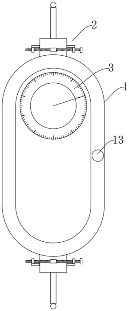
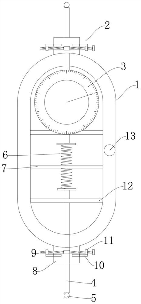
[0036] Measuring ball selection: install the measuring balls that match the internal gear to be tested on the telescopic testing heads on both sides of the device according to the rod spacing standard on the drawing;

[0037] Step two:

[0038] Gauge zero calibration:

[0039] Use a standard ring gauge to zero the dial indicator according to the rod spacing in the drawing;

[0040] Step three:

[0041] Fixture placement and leveling:

[0042] Place the device in the ring gear so that the measuring ball is against the tooth groove, and observe the level bubble to put the device in the right position;

[0043] Step four:

[0044] Fixing and reading of the gage:

[0045] By rotating the control screw rods on both sides of the inspection tool, the connecting nuts are driven to move relative to each other, so that the two-way fixed clamping rod clamps and fixes the telescopic detection head, and then the reading is performed.

[0046] Through the above met...

Embodiment 2

[0048] The staff sticks the measuring stick to both sides of the tooth alveolar, and then uses the measuring block or inner micrometer to measure the reading.

[0049] The measurement process by the above method is cumbersome, has high technical requirements for the staff, and cannot be applied to different types of internal gears, resulting in insufficient measurement accuracy and low efficiency.

[0050] During specific use, the staff installs the corresponding measuring ball 5 according to the detection of the internal gear, uses a standard ring gauge to zero the dial indicator 3 according to the rod spacing of the drawing, and then places the device in the ring gear to make the measuring ball 5 Under the action of the spring 7, it resists the tooth groove, and the device is placed in the right position through the level bubble 13, and then the connecting nut 11 is driven to move relatively by rotating the control screw 9, and the two-way fixed clamping rod 10 is driven to c...


PUM


Abstract

The invention discloses an inner gear ring rod spacing detection tool, which comprises a stable high-efficiency detection tool shell, a bidirectional stable fastening assembly, a dial indicator, a telescopic detection head and a measurement ball. The use method comprises the following steps: step 1, carrying out measurement ball selection; step 2, carrying out zero calibration of a detection tool;step 3, placing and leveling the detection tool; and step 4, fixing and reading of the detection tool. The invention belongs to the field of rod spacing measurement of tooth shapes of internal splines of gear rings. According to the inner gear ring rod spacing detection tool and the use method thereof, elastic telescoping and fixed limiting effects of a telescoping detection head are realized; the measurement process of the rod spacing of the whole internal tooth gear is simplified; convenience for measuring personnel to use is provided; the detection efficiency is improved, the bidirectionalfixing effect is achieved, the stability of a telescopic detection head is higher, deviation of a measurement result caused by deviation is avoided, and the precision is improved; meanwhile, the technical requirements for detection personnel are reduced, and the measurement application range of the whole device is wider.

Description

technical field [0001] The invention belongs to the field of bar spacing measurement of spline tooth shape in a ring gear, and specifically refers to a checker for the bar spacing of an inner ring gear and a using method thereof. Background technique [0002] The way to measure the meshing of one internal gear with another gear is to measure the rod spacing of the internal gear, that is, the distance between two opposing pitch circles. Due to the large distance between the tooth shape detection rods inside the inner ring gear, the detection is time-consuming and laborious, and the efficiency is low. It is necessary to use a measuring rod to stick to both sides of the tooth groove and then measure it with a measuring block or an inner micrometer. Vibration of the head or insufficient fixation of the instrument will also lead to insufficient measurement accuracy. Contents of the invention [0003] In order to solve the above-mentioned existing problems, the present inventio...

Claims


Application Information

Patent Timeline
Patent Type & Authority Applications(China)
IPC IPC(8): G01B5/14
CPCG01B5/14
Inventor 朱晓东
Owner 江苏金卡汽车部件有限公司
Why Eureka
Try Eureka