
Display panel

A display panel and plane technology, applied in static indicators, instruments, identification devices, etc., can solve problems such as capacitive coupling, and achieve the effect of offsetting the influence of capacitive coupling, improving the display effect, and avoiding capacitive coupling.

Inactive Publication Date: 2020-09-15
WUHAN CHINA STAR OPTOELECTRONICS TECH CO LTD
View PDF6 Cites 2 Cited by
  • Summary
  • Abstract
  • Description
  • Claims
  • Application Information

AI Technical Summary

Problems solved by technology

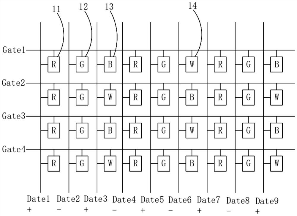
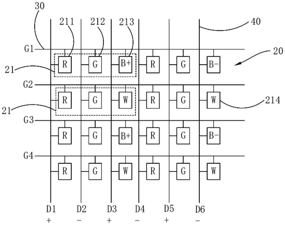
[0004] The embodiment of the present application provides a display panel to solve the problem that in an existing display panel, when a pixel is charged with a voltage under a pure blue screen, the correspondingly connected blue sub-pixels on each Gate line are charged with the same polarity. Prone to technical problems with capacitive coupling

Method used


Image

  • Display panel
  • Display panel
  • Display panel

Examples


Embodiment Construction

[0029] The technical solutions in the embodiments of the present application will be clearly and completely described below in conjunction with the drawings in the embodiments of the present application. Apparently, the described embodiments are only some of the embodiments of this application, not all of them. Based on the embodiments in this application, all other embodiments obtained by those skilled in the art without making creative efforts belong to the scope of protection of this application.

[0030] In the description of the present application, it should be understood that the terms "center", "longitudinal", "transverse", "length", "width", "thickness", "upper", "lower", "front", " Orientation indicated by rear, left, right, vertical, horizontal, top, bottom, inside, outside, clockwise, counterclockwise, etc. The positional relationship is based on the orientation or positional relationship shown in the drawings, which is only for the convenience of describing the a...


PUM


Abstract

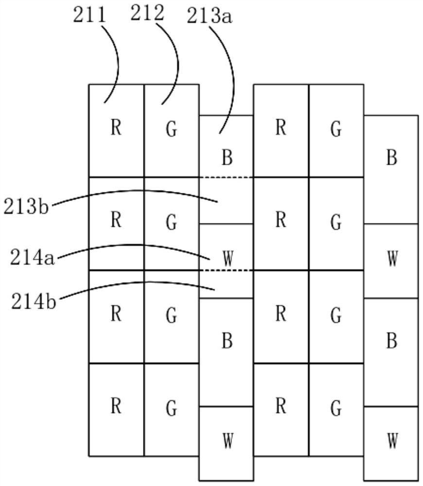
The invention discloses a display panel which comprises a pixel array and scanning lines, the pixel array comprises a plurality of pixel rows, each pixel row comprises a plurality of pixel groups arranged in the row direction, the plurality of scanning lines are arranged along the column direction, each scanning line is correspondingly connected with one pixel row, in the nth pixel row, each pixelgroup comprises a red sub-pixel, a green sub-pixel and a blue sub-pixel, and in the (n+1)th pixel row, each pixel group comprises a red sub-pixel, a green sub-pixel and a white sub-pixel, and n is apositive integer greater than or equal to 1. Under pure blue screen, when the data lines carry out voltage charging on the sub-pixels, each scanning line connected with the B sub-pixels is connected with the B sub-pixels with positive polarity and the B sub-pixels with negative polarity, the influence of capacitive coupling can be counteracted, the problem that capacitive coupling occurs when thesub-pixels carry out voltage charging can be avoided, and the display effect is improved.

Description

technical field [0001] The present application relates to the field of display technology, and in particular to a display panel. Background technique [0002] Currently, in the pixel structure of a display panel, each pixel unit generally includes a red sub-pixel 11 , a green sub-pixel 12 and a blue sub-pixel 13 . Such as figure 1 As shown, in order to enhance the screen brightness ratio and color mixing effect of the display panel, it is proposed in the industry to add white sub-pixels 14 to the pixel structure of the display panel, and arrange the blue sub-pixels 13 in two adjacent columns in a row direction. [0003] However, the Date line (including Date1, Date2....Date9) charges a column of pixels corresponding to the connection. ) are all charged with the same polarity, which is prone to problems such as capacitive coupling. Contents of the invention [0004] The embodiment of the present application provides a display panel to solve the problem that in an existin...

Claims


Application Information

Patent Timeline
Patent Type & Authority Applications(China)
IPC IPC(8): G09F9/30G09G3/20
CPCG09F9/30G09G3/20
Inventor 许作远
Owner WUHAN CHINA STAR OPTOELECTRONICS TECH CO LTD
Learn More