
Hydrogen fuel cell air path air flow control device and method

A fuel cell and air flow technology, applied in fuel cells, circuits, electrical components, etc., can solve the problems of flow and pressure fluctuations, difficulty in achieving stability, long response time, etc., to offset coupling effects, increase responsiveness and use Effects of improving life and responsiveness

Active Publication Date: 2020-02-11
WEICHAI POWER CO LTD
View PDF4 Cites 5 Cited by
  • Summary
  • Abstract
  • Description
  • Claims
  • Application Information

AI Technical Summary

Problems solved by technology

[0005] 1. In the multi-input and multi-output system, the PID control often has a coupling situation. When the PID control is implemented in the flow control and pressure control of the air system, it is easy to have a coupling control situation. Therefore, under the coupling control condition, the flow and pressure will be controlled. fluctuating, difficult to achieve stability
[0006] 2. The combination of table lookup feedforward control and PID control in basic working conditions is greatly affected by boundary conditions and physical characteristics. The combination of table lookup feedforward control and PID control in basic working conditions sometimes has a longer response time
[0007] 3. In order to effectively eliminate the coupling and meet the stable control under various conditions, ordinary PID control must design multiple sets of P and I parameters to meet the control of multiple conditions and multiple conditions, so the calibration workload is relatively large

Method used


Image

  • Hydrogen fuel cell air path air flow control device and method
  • Hydrogen fuel cell air path air flow control device and method
  • Hydrogen fuel cell air path air flow control device and method

Examples


Embodiment Construction

[0028] Exemplary embodiments of the present disclosure will be described in more detail below with reference to the accompanying drawings. Although exemplary embodiments of the present disclosure are shown in the drawings, it should be understood that the present disclosure may be embodied in various forms and should not be limited by the embodiments set forth herein. Rather, these embodiments are provided for more thorough understanding of the present disclosure and to fully convey the scope of the present disclosure to those skilled in the art.

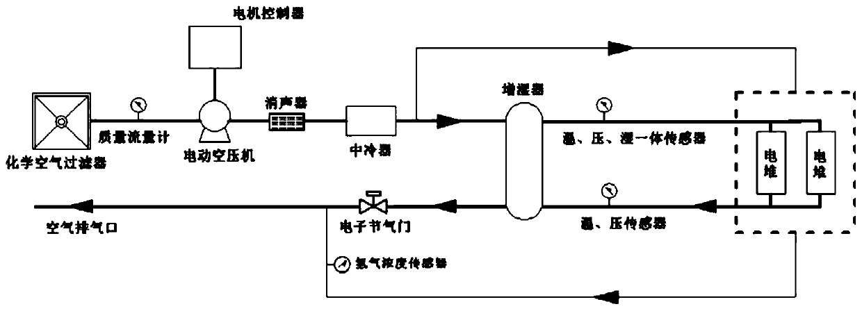
[0029] Such as figure 1 As shown in the air circuit structure diagram, a hydrogen fuel cell air circuit air flow control device of the present invention includes: sequentially connected chemical air filter, electric air compressor, muffler, intercooler, humidifier, electronic throttle . The first input end of the humidifier is connected to the intercooler, the first output end is connected to the electronic throttle, the second ou...


PUM


Abstract

The invention discloses a hydrogen fuel cell air path air flow control device and method. The device comprises a chemical air filter, an electric air compressor, a silencer, an intercooler, a humidifier and an electronic throttle valve which are connected in sequence. The method comprises the following steps of: sending a set rotating speed signal to a compressor controller based on a model control module according to a set fresh air amount and a mass correction coefficient of an I integral module, enabling the compressor controller to send a compressor rotating speed signal to an air inlet system according to the set rotating speed signal, enabling the air inlet system to work according to the compressor rotating speed signal and measure the actual air inlet amount of the air inlet system, and enabling the I integral module to update the mass correction coefficient according to the set fresh air amount and the actual air inlet amount. The device and the method have the advantages thatthe coupling influence of a multiple-input-multiple-output system can be effectively counteracted, the responsiveness and the stability of air flow control are improved, then the power output responsiveness of the fuel cell is improved, the service life of the fuel cell is prolonged, and the control robustness is improved.

Description

technical field [0001] The invention belongs to the technical field of hydrogen fuel cells, and in particular relates to a hydrogen fuel cell air circuit air flow control device and method. Background technique [0002] Existing fuel cell product control technologies are still in the exploratory stage. Air flow control usually adopts traditional PID control, or PID control combined with table look-up feed-forward control based on working conditions. These two types of control are usually used For single input and output control systems. [0003] Existing flow control schemes cannot be effectively implemented in multiple-input and multiple-output systems, especially when joint regulation of pressure and flow is required. Coupling control will make flow and pressure control difficult to reach a steady state. Therefore, multiple-input and multiple-output systems It is difficult to use the ordinary PID method to carry out effective and stable control when controlling. [0004]...

Claims


Application Information

Patent Timeline
IPC IPC(8): H01M8/04746H01M8/04992
CPCH01M8/04753H01M8/04992Y02E60/50
Inventor 陈文淼江楠鹿文慧张家林王盼盼王毓源
Owner WEICHAI POWER CO LTD
Learn More