
Array substrate, driving method thereof, and display device

An array substrate and additional signal technology, applied in static indicators, optics, instruments, etc., can solve the problems of reducing the service life of the display panel, increasing the power consumption of the display panel, and increasing the production cost.

Active Publication Date: 2016-08-10
BOE TECH GRP CO LTD +1
View PDF3 Cites 0 Cited by
  • Summary
  • Abstract
  • Description
  • Claims
  • Application Information

AI Technical Summary

Problems solved by technology

However, this method will increase the power consumption of the display panel, reduce the service life of the display panel, and increase the production cost

Method used


Image

  • Array substrate, driving method thereof, and display device
  • Array substrate, driving method thereof, and display device
  • Array substrate, driving method thereof, and display device

Examples


Embodiment Construction

[0026] The following will clearly and completely describe the technical solutions in the embodiments of the present invention with reference to the accompanying drawings in the embodiments of the present invention. Obviously, the described embodiments are only some, not all, embodiments of the present invention. Based on the embodiments of the present invention, all other embodiments obtained by persons of ordinary skill in the art without making creative efforts belong to the protection scope of the present invention.

[0027] An embodiment of the present invention provides an array substrate, such as Figure 4 As shown, it may include: at least one pixel unit defined by crossing gate lines 10 and data lines 20 , and the array substrate may also include at least one additional signal line 21 .

[0028] The additional signal line 21 may intersect with the pattern of the common electrode layer to form an additional capacitor C.

[0029] The additional capacitance C can be used...


PUM


Abstract

Disclosed are an array substrate, a driving method therefor, and a display apparatus. The array substrate comprises at least one pixel unit (30) defined by crosswise gate lines (10) and data lines (20), and comprises at least one additional signal line (21). The additional signal line (21) and a pattern of a common electrode layer are intersected to form an additional capacitor. The additional capacitor is used for counteracting the coupling effect of a parasitic capacitor formed by the crosswise pattern of the common electrode layer and the data line (20). Therefore, the picture display quality is improved.

Description

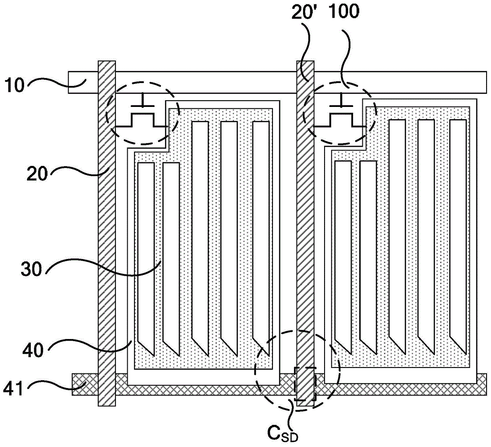
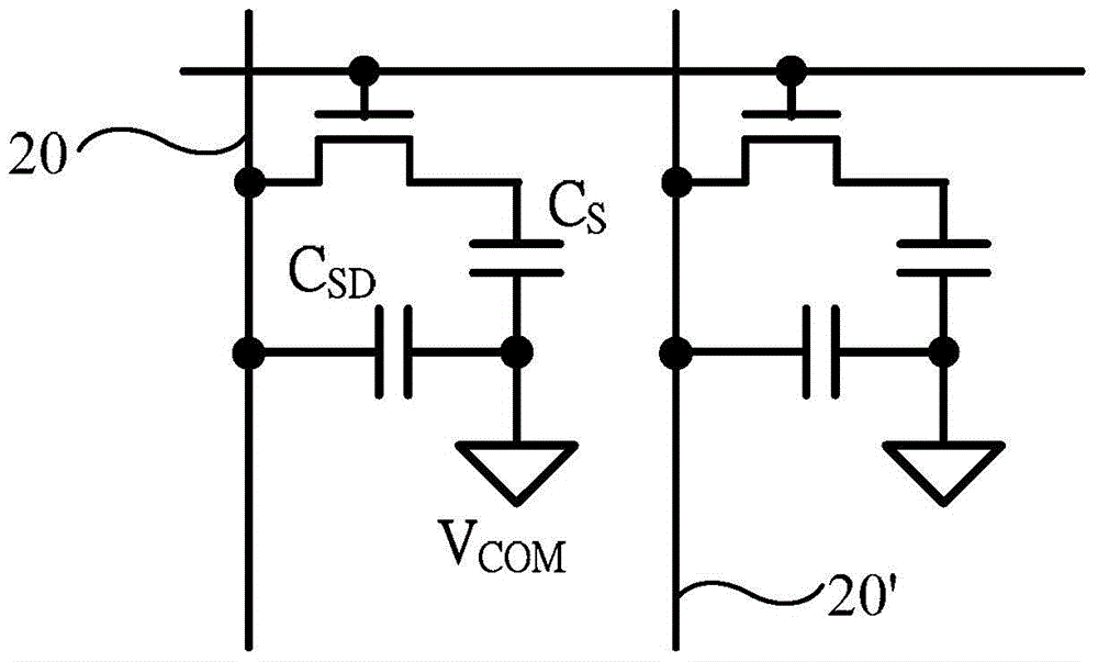
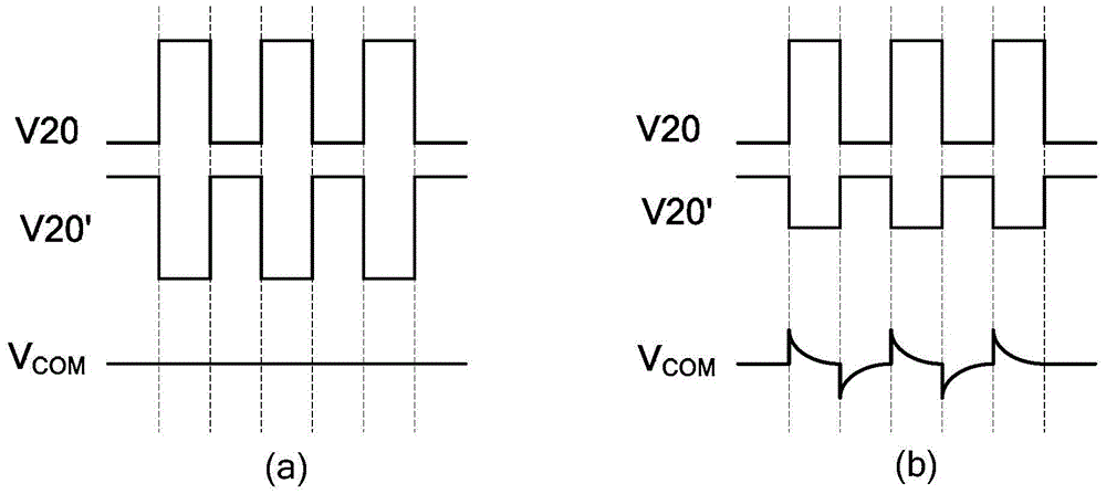
technical field [0001] The present invention relates to the field of display technology, in particular to an array substrate, a driving method thereof, and a display device. Background technique [0002] TFT-LCD (Thin Film Transistor Liquid Crystal Display, Thin Film Transistor Liquid Crystal Display), as a flat panel display device, has become more and more popular due to its small size, low power consumption, no radiation and relatively low production cost. It is widely used in the field of high-performance display. [0003] TFT-LCD is mainly composed of an array substrate and a color filter substrate formed in a box. Among them, the array substrate such as figure 1 What is shown includes: gate lines 10 and data lines 20 (20') intersecting horizontally and vertically, and the gate lines 10 and data lines 20 (20') intersect to define a pixel unit. Each pixel unit includes a TFT 100 , a pixel electrode 30 and a common electrode 40 , and the common electrode line 41 is use...

Claims


Application Information

Patent Timeline
Patent Type & Authority Patents(China)
IPC IPC(8): G02F1/1362G02F1/1368G02F1/133H01L23/522
CPCG02F1/136286G09G3/3659G09G2300/0876G02F1/13606
Inventor 赖意强
Owner BOE TECH GRP CO LTD
Learn More