Specially-shaped part clamping equipment of numerically-controlled lathe
A CNC lathe and special-shaped technology, which is applied in the field of tooling and fixtures, can solve the problems of inability to directly clamp special-shaped parts, difficult to ensure production accuracy, and reduce production quality, and achieve the effect of firm clamping, reliable production quality, and guaranteed production quality.
- Summary
- Abstract
- Description
- Claims
- Application Information
AI Technical Summary
Problems solved by technology
Method used
Image

Examples
Embodiment
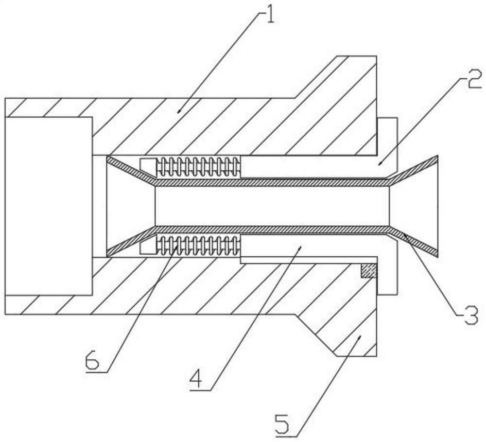
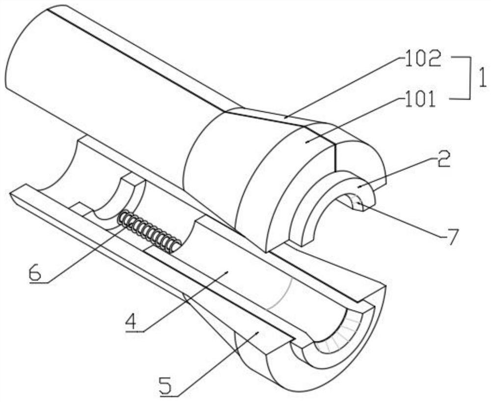
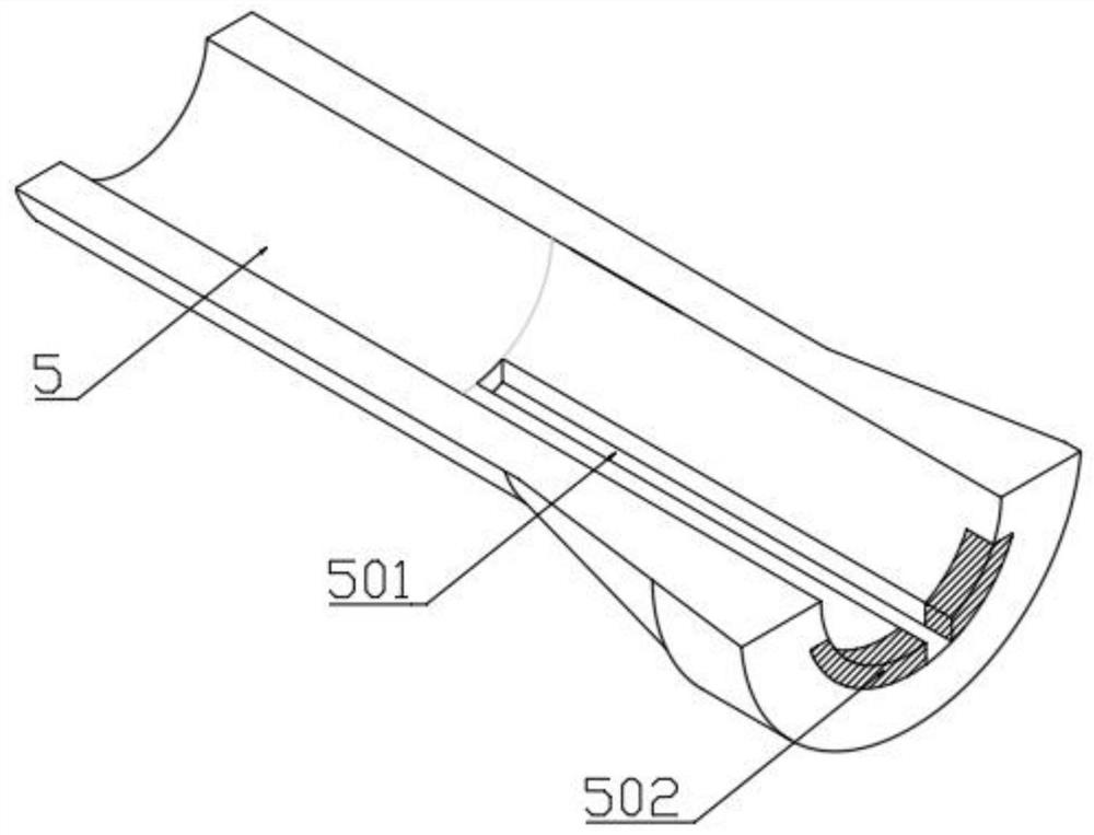
[0028] as attached figure 1 to attach Figure 4 Shown:
[0029] The invention provides a clamping device for special-shaped parts of a CNC lathe, which includes an upper splint 1, the upper splint 1 and the lower splint 5 both have a half-cylindrical tubular structure, and the front ends of the upper splint 1 and the lower splint 5 are both half-shaped A trumpet-shaped distribution; the upper clamping plate 1 includes a first clamping piece 101 and a second clamping piece 102, the first clamping piece 101 and the second clamping piece 102 are quarter ring structures, when the upper clamping plate 1 and the lower clamping plate 5 are paired When the special-shaped casing part 3 is clamped, the first clamping piece 101 and the second clamping piece 102 are in a tight fit state; the upper splint 1 is provided with an upper spacer 2 inside a half cylindrical lumen; the lower splint 5 two There is a lower block 4 inside the one-third cylindrical lumen; the upper block 2 and the l...
PUM
 Abstract
Description
Claims
Application Information