
3D printing material spraying device

A 3D printing and material spraying technology, applied in the field of 3D printing, can solve the problems of unnatural connection at corners, defects in adaptive adjustment of transmission stability, affecting the appearance of products, etc., to ensure continuity and good material guidance. material effect

Inactive Publication Date: 2020-09-18
新乡医学院三全学院
View PDF8 Cites 0 Cited by
  • Summary
  • Abstract
  • Description
  • Claims
  • Application Information

AI Technical Summary

Problems solved by technology

In the process of printing with the above method, since the trajectory of the 3D printing nozzle is a straight line, the printing at the corner of the product will cause unnatural and unsmooth connection at the corner, which will affect the appearance of the product. Seriously, Even affect the quality and use of the product
[0004] Chinese patent (notification number CN208305804U) discloses a 3D printing material spraying device and 3D printing equipment, although it can make the appearance of the product formed at the corner of the printed product better connected, and more natural and smooth, but in terms of transmission stability , Coherent and high-quality material guide, and adaptive adjustment have defects

Method used


Image

  • 3D printing material spraying device
  • 3D printing material spraying device
  • 3D printing material spraying device

Examples


Embodiment 1

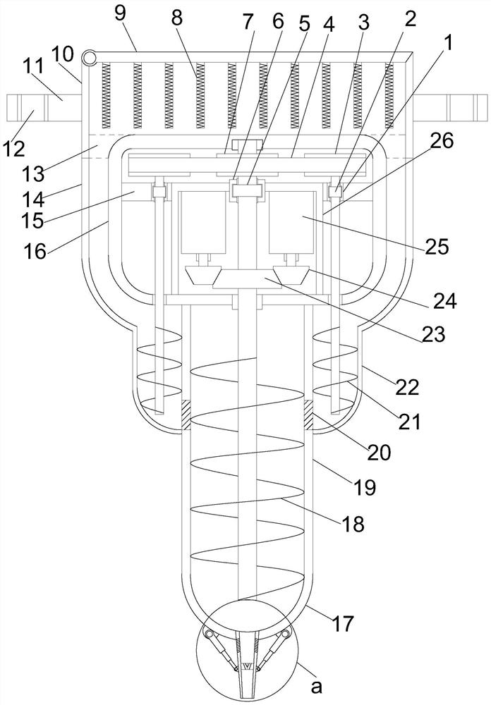
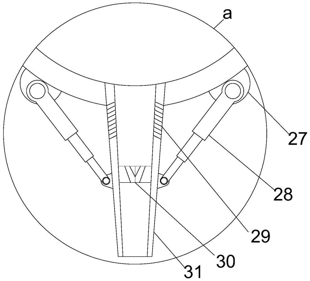
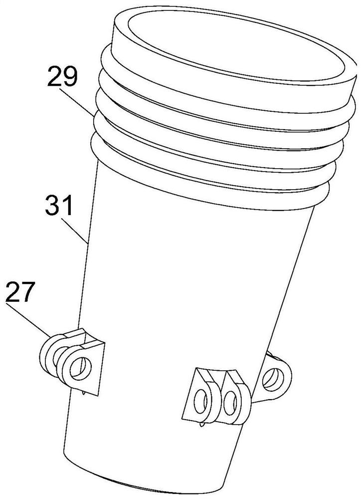
[0022] see Figure 1~3 , in an embodiment of the present invention, a 3D printing material spraying device includes a vertically arranged transmission installation cylinder 16, a support installation cylinder 10 is vertically provided on the upper end of the transmission installation cylinder 16, and a support installation cylinder 10 is symmetrically provided on the outside of the support installation cylinder 10. The mounting plate 11 and the supporting mounting plate 11 are provided with fixed mounting holes 12. The upper end of the supporting mounting cylinder 10 is equipped with a rotating cover plate 9 through a rotating shaft provided in the upper left corner. The lower side array of the rotating cover plate 9 is provided with several The electric auxiliary heating column 8, the middle position of the lower end of the transmission installation cylinder 16 is vertically provided with a main material installation cylinder 19, and the outer side of the upper half of the mai...

Embodiment 2

[0025] On the basis of Embodiment 1, by controlling the expansion and contraction of the swing telescopic column 28 and coordinating with the swing installation frame 27, the swing of the tapered discharge pipe is realized. Material operation, so that the device can change the angle of spraying material.


PUM


Abstract

The invention relates to the field of 3D printing, in particular to a 3D printing material spraying device. The device comprises a transmission mounting cylinder arranged vertically, wherein the upperend of the transmission mounting cylinder is vertically provided with a support mounting cylinder, the outside of the support mounting cylinder is symmetrically provided with support mounting plates,fixed mounting holes run through the support mounting plates, the upper end of the support mounting cylinder is installed with a rotating cover plate through a rotating shaft set in the upper left corner, the lower end of the transmission mounting cylinder is vertically provided with a main material guide mounting cylinder at the central position, and two sets of sub guide mounting cylinders aresymmetrically arranged on the outer side of the upper half of the main material guide mounting cylinder. Through the driving of a synchronous bevel gear, the device has a high torque and stable transmission power. Through the transmission of a synchronous belt, first-stage spiral pressurized material guide and second-stage spiral pressurized material guide are combined for the material to make thedevice have a good material guiding effect, so as to guarantee the continuity of printing and spraying. At the same time, the angle of spraying is changed, so that the device can adapt to different spraying needs.

Description

technical field [0001] The invention relates to the field of 3D printing, in particular to a 3D printing material spraying device. Background technique [0002] 3D printing is a kind of rapid prototyping technology. It is a technology based on digital model files, using powdered metal, plastic, biomaterials, etc., to construct objects by layer-by-layer printing. 3D printing usually uses digital Technical material printer to achieve. [0003] In the existing 3D continuous printing process, the trajectory of the 3D printing nozzle is a straight line. When printing, the 3D printing nozzle always prints in one direction. In the process of printing with the above method, since the trajectory of the 3D printing nozzle is a straight line, the printing at the corner of the product will cause unnatural and unsmooth connection at the corner, which will affect the appearance of the product. Seriously, Even affect the quality and use of the product. [0004] Chinese patent (notificat...

Claims


Application Information

Patent Timeline
Patent Type & Authority Applications(China)
IPC IPC(8): B29C64/209B29C64/321B33Y30/00B33Y40/00
CPCB33Y30/00B33Y40/00B29C64/209B29C64/321
Inventor 靳瑞霞袁志垚张改改
Owner 新乡医学院三全学院
Learn More