Automatic guide trolley

A technology for automatically guiding trolleys and car bodies. It is used in motor vehicles, transportation and packaging. It can solve the problems of high fatigue and easy damage of elastic parts, and achieve the effect of precise movement.

Active Publication Date: 2020-09-18
YUNNAN ZHUOPEI TECH
View PDF4 Cites 4 Cited by
  • Summary
  • Abstract
  • Description
  • Claims
  • Application Information

AI Technical Summary

Problems solved by technology

[0004] The purpose of the present invention is to provide an automatic guided trolley to solve the technical problem in the prior art that the damping performanc

Method used


Image

  • Automatic guide trolley
  • Automatic guide trolley
  • Automatic guide trolley

Examples


specific Embodiment 1

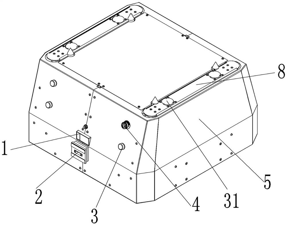
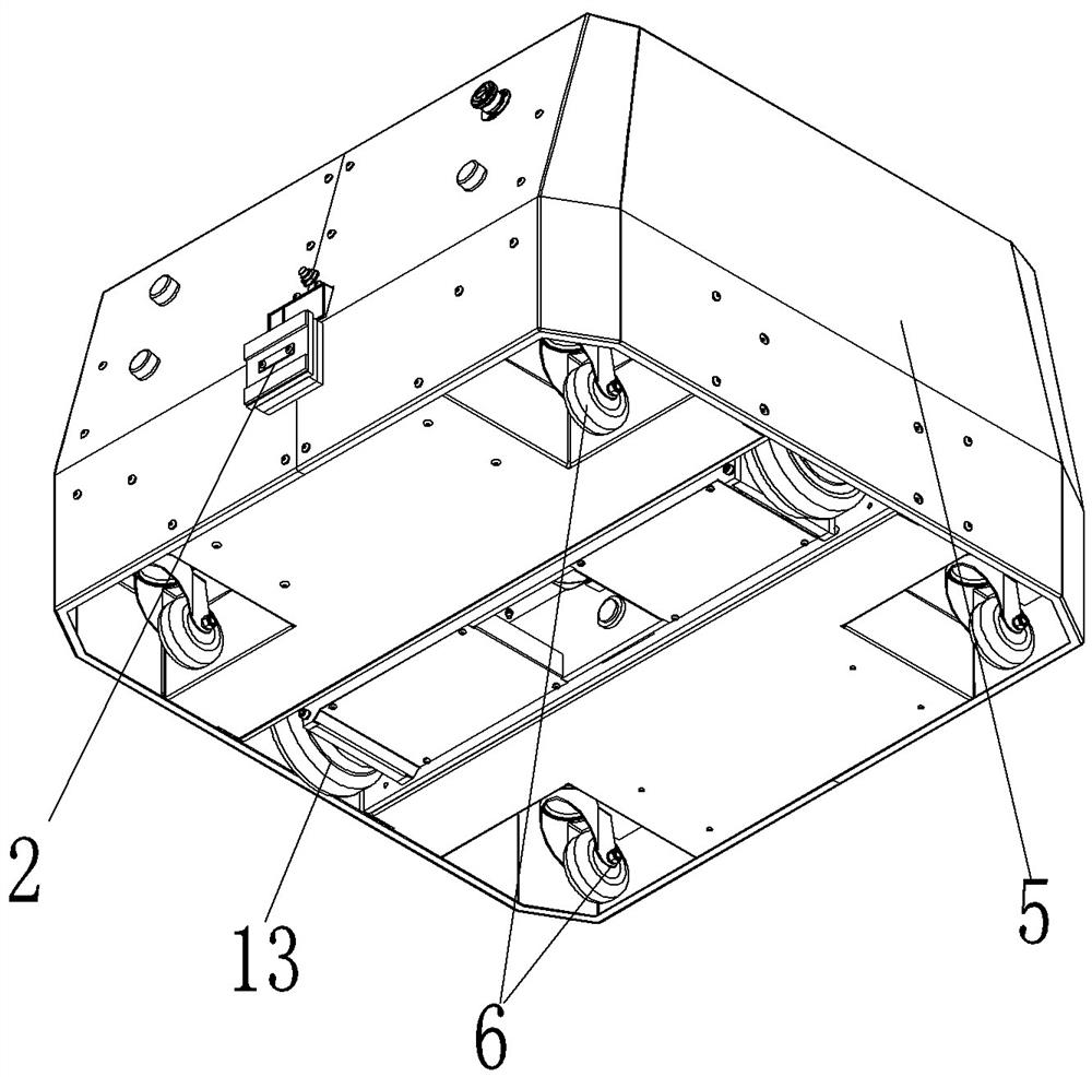
[0053] like Figure 1 to Figure 10 As shown, the automatic guided vehicle includes a car body 7, a casing 5 is arranged outside the car body 7, and traveling wheels are installed on the lower part of the car body 7 to realize the movement of the car body.

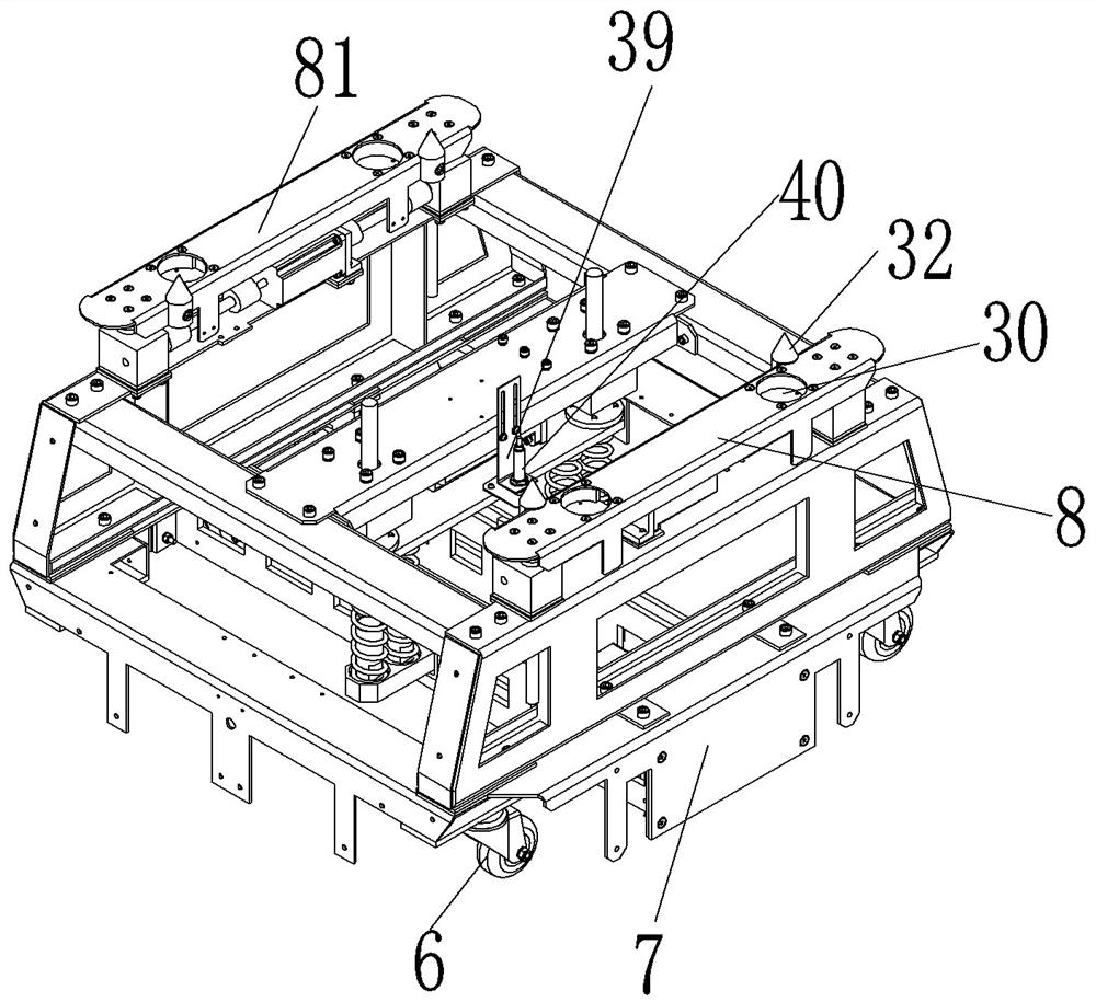
[0054] The top of the car body 7 is provided with a lifting platform 8 for lifting up to carry items to be transported. Specifically, the output part of the lifting platform is two strip-shaped supports 81. There are elongated holes for the passage of the strip supports 81 . Moreover, to facilitate positioning and assembly, a tapered positioning post 32 is provided on the bar-shaped support 81 for positioning and assembling with the corresponding tray.

[0055] In addition, an installation slot 30 is provided on the strip support member 81 , and a load cell 31 is provided in the installation slot 30 to weigh the item to be transported when lifting the heavy object.

[0056] An obstacle avoidance sensor switch 1, a chargin...

Embodiment 1

[0078] The wheel bracket in Embodiment 1 includes a driving wheel mounting frame and a support member, and both of them can rotate relative to each other, which makes the driving wheel mounting frame not only float up and down, but also rotate and adjust around the circular sleeve. The difference between the automatic guided vehicle provided in this embodiment and Embodiment 1 is that in this embodiment, the wheel bracket is a frame structure, the driving wheel is directly installed on the wheel bracket, and the wheel bracket can only move up and down along the car body. Floating, cannot be adjusted by rotation.

specific Embodiment 3

[0080] Compared with Embodiment 1, the difference between this embodiment and Embodiment 1 is that the lifting drive mechanism in this embodiment adopts an electric push rod mechanism instead of the screw elevator in Embodiment 1, but attention should be paid to the support of the electric push rod mechanism. strength.

[0081] In addition, in this embodiment, the support includes a front support shaft and a rear support shaft arranged at intervals along the front-to-back direction. In other embodiments, only one support may be provided. At this time, the front and rear ends of the support are respectively Hinged on the front and rear side plates of the drive wheel installation frame, the support plate can be located between the front and rear side plates, or only one support plate can be provided. At this time, a rectangular hole is arranged on the support plate, and the front and rear ends of the support The part in between is a rectangular shaft section, and the rectangular...


PUM


Abstract

The invention relates to an automatic guide trolley, which comprises a trolley body and a wheel support, wherein driving wheels are installed at the bottom of the wheel support, an elastic suspensionstructure is arranged between the trolley body and the wheel support, and the elastic suspension structure comprises a top supporting plate and a suspension elastic piece. A lifting driving mechanismis installed on the vehicle body and is in transmission connection with the top supporting plate so as to drive the top supporting plate to reciprocate in the vertical direction. The upper end of thesuspension elastic piece is matched with the top supporting plate, and the lower end of the suspension elastic piece is matched with the wheel support so as to apply elastic acting force enabling thetop supporting plate and the wheel support to be away from each other. Floating adjustment of the wheel support is achieved through the elastic suspension structure. Due to the fact that the top supporting plate can be driven by the lifting driving mechanism to ascend and descend, the elastic damping performance of the whole elastic suspension structure can be adjusted in cooperation with the suspension elastic piece, and the problem that the elastic piece is high in fatigue degree and prone to damage due to complete dependence on the elastic piece is solved.

Description

technical field [0001] The invention relates to an automatic guided trolley. Background technique [0002] Automatic guided vehicles are also widely used in service industry, manufacturing industry, express delivery industry, transportation industry and other industries. In the prior art, in order to improve the passing stability of the guided vehicles, elastic suspensions are mostly used, such as the driving wheel suspension damping mechanism of the AGV trolley disclosed in the Chinese invention patent application with the application publication number CN110722943A, which includes a fixed plate and a wheel bracket , and a damping unit arranged between the two, the damping unit includes a guide shaft, one end of the guide shaft is fixedly connected with the wheel bracket, the other end is slidably assembled with the fixing plate, the guide shaft is covered with an elastic member, and the two ends of the elastic member Correspondingly assembled with the fixed plate and the ...

Claims


Application Information

Patent Timeline
IPC IPC(8): B62D63/02B62D63/04
CPCB62D63/02B62D63/04
Inventor 潘勇孙中春杨恒杨应春
Owner YUNNAN ZHUOPEI TECH
Why Eureka
Try Eureka