Hydraulic power self-lifting anti-flood wall

A technology of self-lifting and flood control walls, applied in dikes, dams, water conservancy projects, etc., can solve the problems of increased flood control costs and manpower input, incalculable losses, and reduced reliability

Pending Publication Date: 2020-09-18
松辽水利委员会流域规划与政策研究中心
View PDF1 Cites 2 Cited by
  • Summary
  • Abstract
  • Description
  • Claims
  • Application Information

AI Technical Summary

Problems solved by technology

This utility model has the following defects: during operation, live working equipment such as sensors are easily damaged under extreme flood conditions, and the probability of equipment function loss increases, reducing its overall reliability, and the losses caused to it will be incalculable ; In addition, sensors, hydraulic cylinders and other equipment need regular maintenance, which in disguise increases flood control costs and manpower input

Method used


Image

  • Hydraulic power self-lifting anti-flood wall
  • Hydraulic power self-lifting anti-flood wall
  • Hydraulic power self-lifting anti-flood wall

Examples


Embodiment Construction

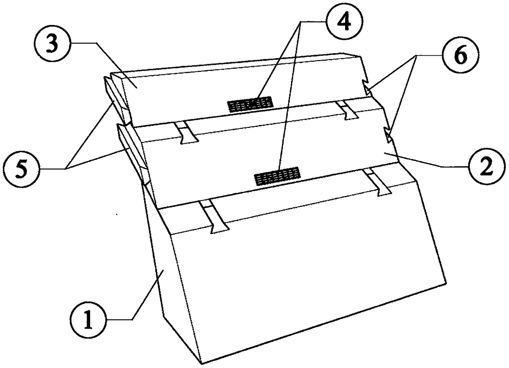
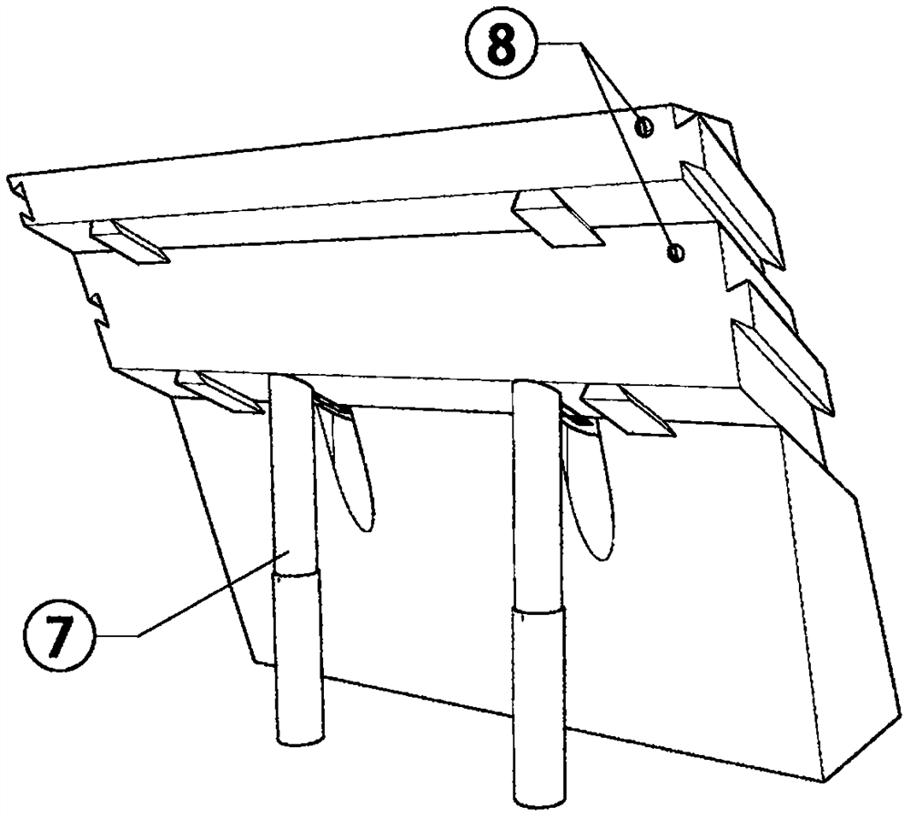
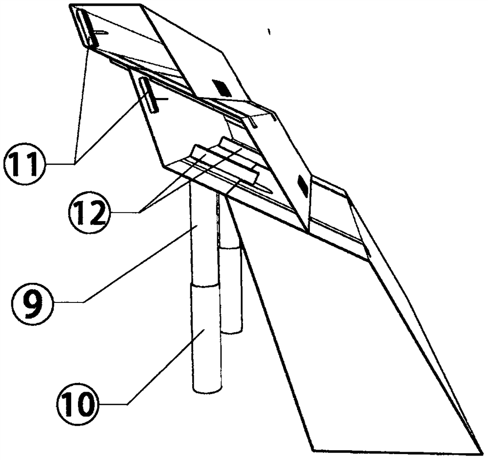
[0017] Embodiments of the present invention will be described in detail below in conjunction with the accompanying drawings. A pedestal layer 1 of a hydraulic self-lifting flood control wall is fixed with a chute structure 6, and the chute structure 6 fits with the limit structure 5 fixed at the bottom of the lifting bottom 2, so that the lifting bottom 2 can Relatively sliding along the upper slope of the base layer 1 without falling off, the lifting bottom layer 2 is fixed with a chute structure 6, and the chute structure 6 fits with the limit structure 5 fixed at the bottom end of the lifting top layer 3, The lifting top layer 3 can slide relatively along the inclined surface of the lifting bottom layer 2 without falling off. An air hole automatic adjustment device 11 is installed, and a supporting contraction device 7 is installed at the bottom end of the lifting bottom layer 2 . The support contraction device 7 comprises a support trigger device 12, a support column I 9 ...


PUM


Abstract

The invention discloses a hydraulic power self-lifting anti-flood wall. The hydraulic power self-lifting anti-flood wall is formed by sequential overlapped installation of a base layer, a lifting bottom layer and a lifting top layer under the cooperation of a sliding groove structure and a limiting structure. A supporting pillar I and a supporting pillar II are sequentially installed at the bottomend of the lifting bottom layer. A supporting triggering device and an air hole automatic adjusting device are installed in the lifting bottom layer. A reset spring bolt in the supporting triggeringdevice is connected with a position fixing support, a reset spring and a linking shaft, and the linking shaft penetrates a spring limiting beam to be connected with a rigid closed supporting structureII. The spring limiting beam is connected with the bottom end of the supporting pillar II through a spring. The hydraulic power self-lifting anti-flood wall is simple in structure, operation runningunder flood conditions is stable and reliable, the anti-flood height and the flow capability are improved, the anti-flood labor is greatly saved, and the peak shifting and preparing time is further provided for downstream flood fighting and emergency rescuing.

Description

technical field [0001] The invention belongs to the technical field of flood control, and in particular relates to a hydraulic self-lifting flood wall. Background technique [0002] Natural floods caused by floods have always been one of the main natural disasters in our country, causing immeasurable losses to economic and social development. Due to the complexity of factors affecting floods and the limitations of human understanding of the natural world, the exact time, location, scale and process of floods cannot be predicted at present. The impact of flood disasters cannot be avoided, and the design of embankment buildings is particularly important in reducing flood losses. [0003] The main variable load in the structural design and reliability analysis of embankment buildings is water pressure, and the water pressure is closely related to the fortification flood level of local buildings. At present, the determination of the fortification flood level of embankments is ...

Claims


Application Information

Patent Timeline
Patent Type & Authority Applications(China)
IPC IPC(8): E02B3/10
CPCE02B3/104
Inventor 陈伟林岚崔亚锋侯琳崔丽艳
Owner 松辽水利委员会流域规划与政策研究中心
Why Eureka
Try Eureka