Supercharge Your Innovation With Domain-Expert AI Agents!

Adjustable automatic valve

An automatic valve and valve body technology, applied in the direction of valve lift, valve details, valve device, etc., can solve the problems of heat group loss, resource waste, and inability to adjust in real time, and achieve the effect of reducing losses

Pending Publication Date: 2020-09-18
戢森
View PDF0 Cites 0 Cited by
  • Summary
  • Abstract
  • Description
  • Claims
  • Application Information

AI Technical Summary

Problems solved by technology

However, because the setting range is generally divided by photo area, and has a certain lag, it cannot be adjusted in real time according to the actual situation of each user, resulting in unreasonable heat distribution, waste of resources and great losses to the thermal group

Method used


Image

  • Adjustable automatic valve
  • Adjustable automatic valve
  • Adjustable automatic valve

Examples


Embodiment Construction

[0028] In order to describe the technical content, structural features, goals and effects of the present invention in detail, the following examples are given to describe the embodiments in conjunction with the accompanying drawings.

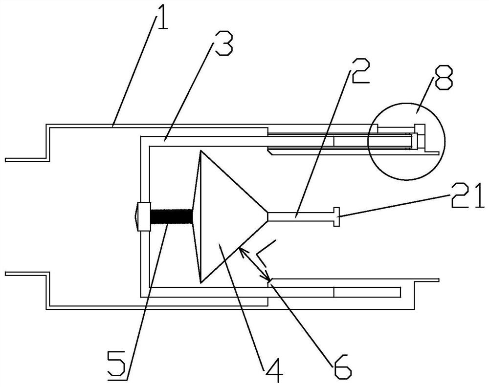
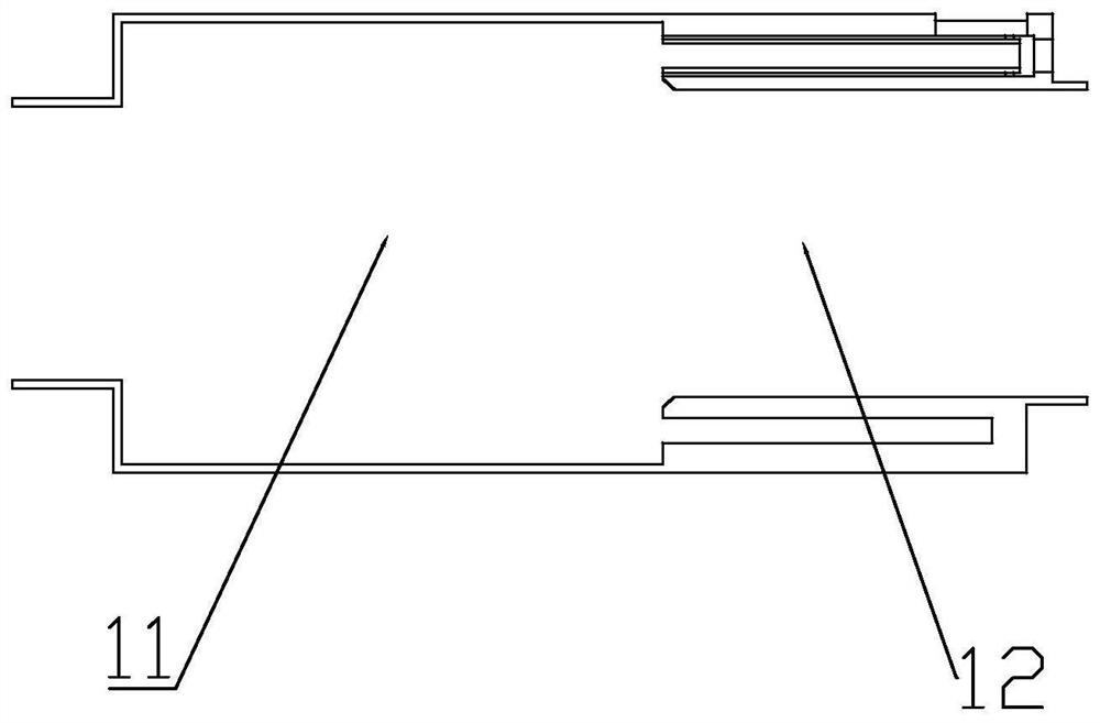
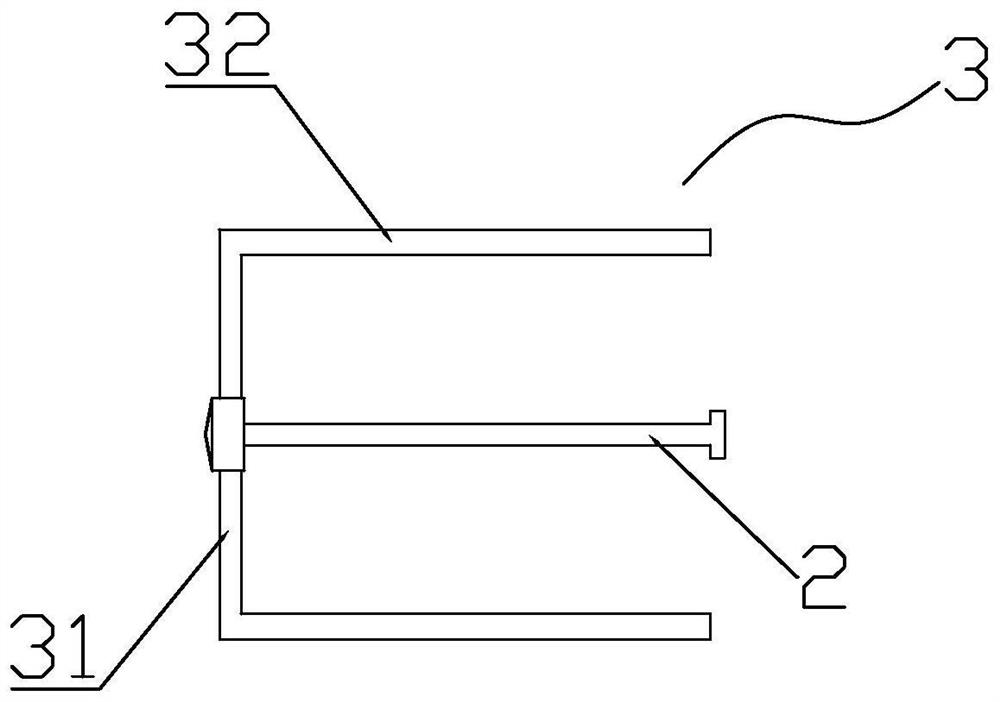
[0029] combine figure 1 and figure 2 , an adjustable automatic valve disclosed by the present invention, comprising a cylindrical valve body 1, a cavity is formed in the valve body 1, an axially arranged optical axis 2 is arranged in the valve body 1, and the optical axis 2 is set on the In the valve body 1, the optical axis 2 is fixedly connected with the bracket 3, and the bracket 3 is flexibly connected with the valve body 1, and the bracket 3 can drive the optical axis 2 to move along the axial direction of the valve body 1;

[0030] A valve head 4 is threaded on the optical axis 2, and a memory metal spring 5 is set on the optical axis 2 between the valve head 4 and the bracket 3; the inner wall of the valve body 1 is also provided with a...


PUM


Abstract

The invention discloses an adjustable automatic valve. The valve comprises a columnar valve body, wherein a cavity is formed in the valve body, and an axially arranged optical shaft is arranged in thevalve body through a bracket, and is fixedly connected with the bracket, and the bracket is movably connected with the valve body, and can drive the optical shaft to move in the axial direction of the valve body; a valve head penetrates the optical shaft, and the optical shaft between the valve head and the bracket is sleeved with a memory metal spring; and a boss is also arranged on the inner wall of the valve body, and is located on one side, away from the memory metal spring, of the boss. After the valve is mounted at inflow water of a heating pipe of each household, the flow of the inflowwater can be automatically adjusted according to the real-time temperature of the inflow water. Besides, a worker can manually increase or decrease the adjustment range according to the actual situation, so that the inflow water situation of a heating system of each household can be adjusted according to the actual situation more intelligently, and the loss caused by excessive heating of heatinggroups is greatly reduced.

Description

technical field [0001] The invention relates to the technical field of heat control, in particular to an adjustable automatic valve. Background technique [0002] In the existing central heating, the thermal power group transports municipal heat to the user's home through pipelines. The medium is generally water, which is a clean and guaranteed heating method. This method is cheap and has relatively high safety performance. In the actual heat transfer process, due to the limitations of various conditions (such as the distance, the height of the floor, etc.), different users have different requirements for the temperature of the heat to the home (in practical applications, it is generally controlled by the temperature and flow of water entering the home. ). Most of the existing flow control is manually set by the staff of the thermal power group according to the area. However, because the setting range is generally divided by photo area, and has a certain lag, it cannot be...

Claims


Application Information

Patent Timeline
Patent Type & Authority Applications(China)
IPC IPC(8): F16K31/70F16K37/00F16K1/00F16K1/32F16K1/38F16K35/06F16K31/60F24D19/10
CPCF16K1/00F16K1/32F16K1/38F16K31/002F16K31/60F16K35/06F16K37/0016F24D19/1015
Inventor 戢森
Owner 戢森
Features
  • R&D
  • Intellectual Property
  • Life Sciences
  • Materials
  • Tech Scout
  • Unparalleled Data Quality
  • Higher Quality Content
  • 60% Fewer Hallucinations
Learn More