Flange installation device and method

A flange installation and flange technology, applied in flange connection, through components, mechanical equipment, etc., can solve the problems of inability to reconstruct pipelines and meet the needs of enterprises, and achieve simple structure, meet the needs of use, and easy to operate. Effect

Active Publication Date: 2022-02-18
HEBEI HUAFENG ENERGY TECH DEV CO LTD
View PDF0 Cites 0 Cited by
  • Summary
  • Abstract
  • Description
  • Claims
  • Application Information

AI Technical Summary

Problems solved by technology

However, in the hazardous chemical area, because hot fire is prohibited in the hazardous chemical area, the conventional welding method cannot be used to carry out pipeline reconstruction in the hazardous chemical area, which cannot meet the needs of enterprises.

Method used


Image

  • Flange installation device and method

Examples


Embodiment Construction

[0023] The following will clearly and completely describe the technical solutions in the embodiments of the present invention with reference to the accompanying drawings in the embodiments of the present invention. Obviously, the described embodiments are only some, not all, embodiments of the present invention. Based on the embodiments of the present invention, all other embodiments obtained by persons of ordinary skill in the art without making creative efforts belong to the protection scope of the present invention.

[0024] Unless otherwise defined, all technical and scientific terms used herein have the same meaning as commonly understood by one of ordinary skill in the technical field of the invention. The terms used herein in the description of the present invention are for the purpose of describing specific embodiments only, and are not intended to limit the present invention.

[0025] see figure 1 , the flange mounting device provided by one embodiment of the present...


PUM


Abstract

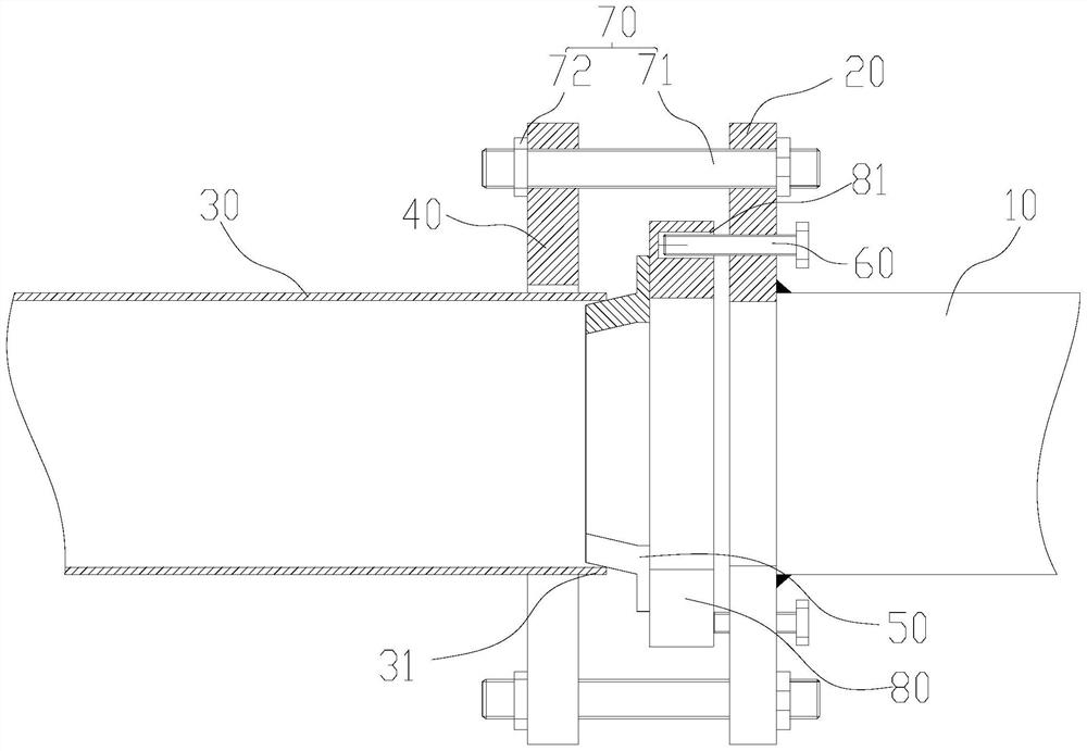
The flange installation device and method claimed in the present invention, the flange installation device includes a first pipeline, a fixed flange, a second pipeline, a movable flange, a taper sleeve, a driving part and a bolt group; the driving part can push the top The taper sleeve acts on the nozzle of the second pipeline, so that the nozzle of the second pipeline is deformed into a bell-shaped shape; the bolt group acts on the fixed flange and the movable flange, and The bolt group can drive the movable flange to squeeze the deformed nozzle on the second pipe and move toward the direction of the fixed flange, so that the movable flange, the taper sleeve and the fixed flange Tight fit in turn. The present invention uses the physical method of extrusion deformation to realize the tight fit between the movable flange, the taper sleeve and the fixed flange, so as to realize the assembly and fixation between the first pipe and the second pipe, so that the flange installation device is suitable for It is used to transform the pipeline in the hazardous chemical area to meet the needs of the enterprise.

Description

technical field [0001] The invention belongs to the technical field related to flange installation, and in particular relates to a flange installation device and method. Background technique [0002] The connection and communication between two pipes is usually fixed by flange installation. Specifically, the flange is welded to the nozzle position of the corresponding pipe, and the two flanges are connected and fixed with bolts and nuts. However, in the hazardous chemical area, since hot fire is prohibited in the hazardous chemical area, the conventional welding method cannot be used to carry out pipeline reconstruction in the hazardous chemical area, which cannot meet the needs of enterprises. Contents of the invention [0003] Based on this, it is necessary to provide a flange installation device and method for the technical problems existing in the prior art. [0004] Specifically, a flange installation device includes a first pipe, a fixed flange fixed to the first pi...

Claims


Application Information

Patent Timeline
Patent Type & Authority Patents(China)
IPC IPC(8): F16L23/028F16L23/032
CPCF16L23/0286F16L23/032
Inventor 许晓波王庆国
Owner HEBEI HUAFENG ENERGY TECH DEV CO LTD
Why Eureka
Try Eureka