Method, device and chip for cross-chip signal synchronization

A signal synchronization and cross-chip technology, applied in the direction of signal generation/distribution, can solve problems such as chip clock signal delay, and achieve the effect of eliminating delay errors

Active Publication Date: 2022-03-11
TECHTOTOP MICROELECTRONICS
View PDF9 Cites 0 Cited by
  • Summary
  • Abstract
  • Description
  • Claims
  • Application Information

AI Technical Summary

Problems solved by technology

[0004] In view of this, the embodiment of the present invention provides a method, device and chip for cross-chip signal synchronization to solve the problem of delay introduced when correcting the chip clock signal

Method used


Image

  • Method, device and chip for cross-chip signal synchronization
  • Method, device and chip for cross-chip signal synchronization
  • Method, device and chip for cross-chip signal synchronization

Examples


Embodiment 1

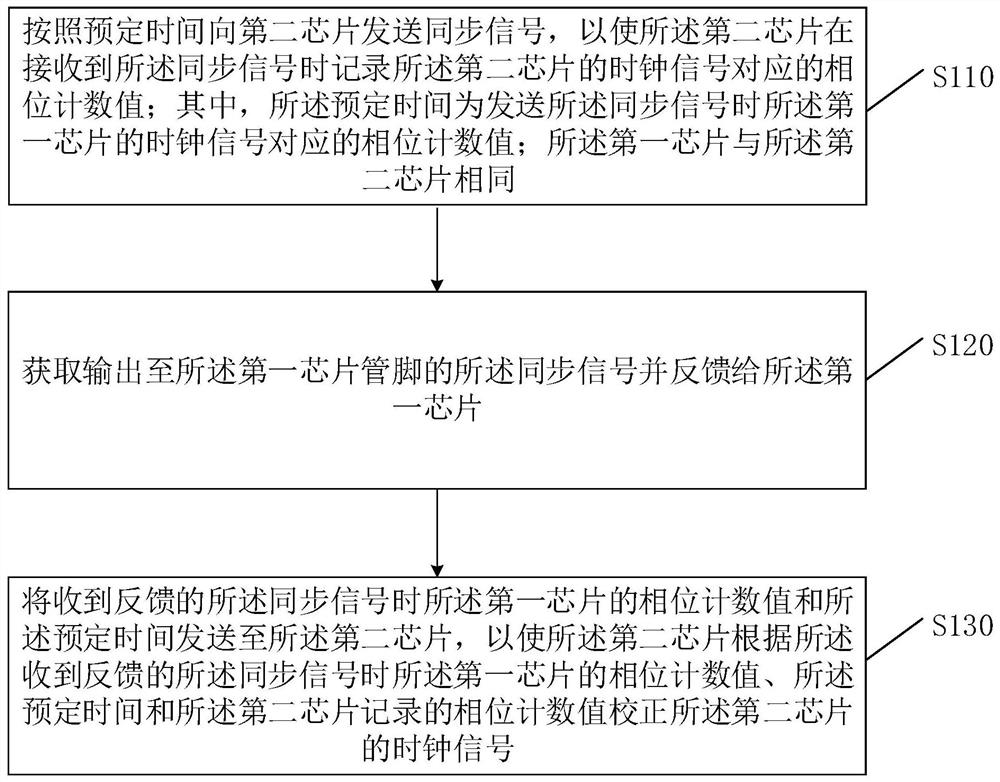
[0041] like figure 1 As shown, it is a schematic flowchart of a method for synchronizing signals across chips provided by Embodiment 1 of the present invention. This embodiment is applicable to the application scenario of synchronously correcting clock signals between two chips, and the method can be executed by a device for synchronizing signals across chips, which can be a chip; in this embodiment of the application, the first chip is used As an executive subject, the method specifically includes the following steps:

[0042] S110. Send a synchronization signal to the second chip according to a predetermined time, so that the second chip records the phase count value corresponding to the clock signal of the second chip when receiving the synchronization signal; The phase count value corresponding to the clock signal of the first chip when the synchronization signal is mentioned; the first chip is the same as the second chip;

[0043] Because in the existing clock correctio...

Embodiment 2

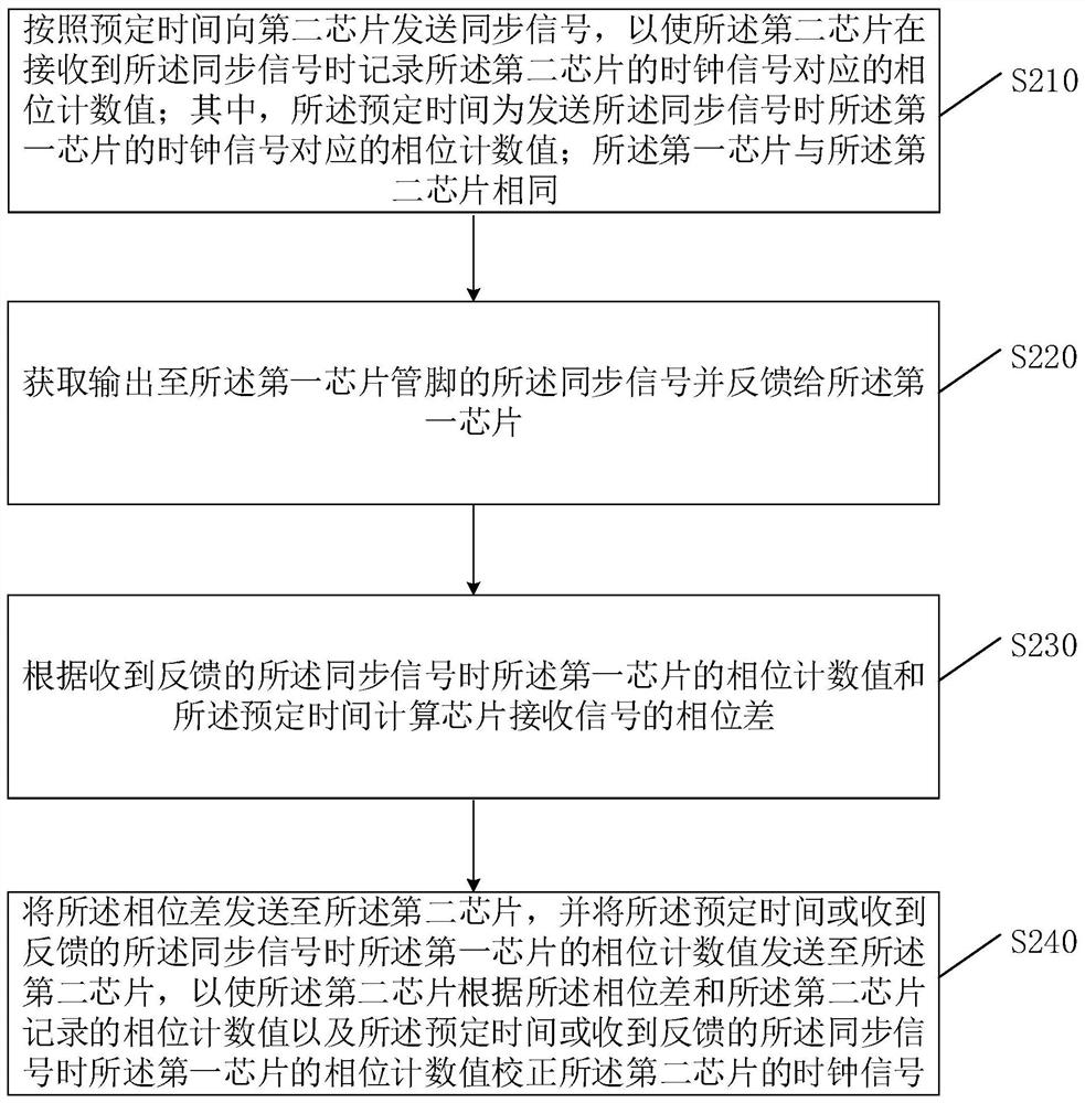
[0055] like figure 2 What is shown is a schematic flowchart of a method for synchronizing signals across chips provided by Embodiment 2 of the present invention. On the basis of the first embodiment, this embodiment also provides another cross-chip signal synchronization method, so as to realize precise synchronization between the first chip and the second chip. The method specifically includes:

[0056] S210. Send a synchronization signal to the second chip according to a predetermined time, so that the second chip records the phase count value corresponding to the clock signal of the second chip when receiving the synchronization signal; wherein, the predetermined time is The phase count value corresponding to the clock signal of the first chip when sending the synchronization signal; the first chip is the same as the second chip;

[0057] When correcting the clock of the second chip, the first chip sends a synchronization signal to the second chip according to the predet...

Embodiment 3

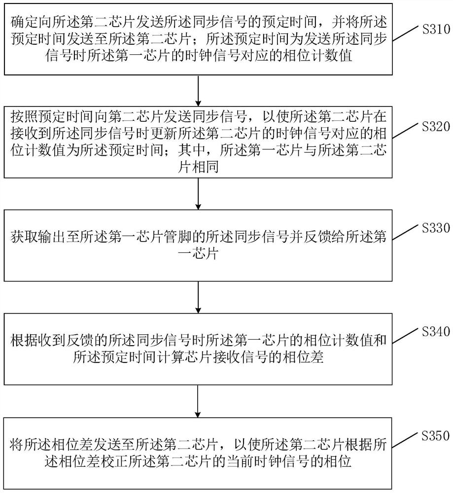
[0070] like image 3 What is shown is a schematic flowchart of a method for synchronizing signals across chips provided by Embodiment 2 of the present invention. On the basis of the second embodiment, this embodiment also provides another cross-chip signal synchronization method, so as to realize precise synchronization between the first chip and the second chip. The method specifically includes:

[0071] S310. Determine a predetermined time for sending the synchronization signal to the second chip, and send the predetermined time to the second chip; the predetermined time is the clock of the first chip when sending the synchronization signal The phase count value corresponding to the signal;

[0072] Specifically, before the first chip sends the synchronization signal to the second chip at the predetermined time, the first chip may predetermine a predetermined time for sending the synchronization signal to the second chip, and send the determined predetermined time to the s...


PUM


Abstract

The present application belongs to the technical field of signal synchronization, and provides a cross-chip signal synchronization method, device, and chip. The first chip is used as the execution subject. The method includes: sending a synchronization signal to the second chip according to a predetermined time, so that The second chip records the phase count value corresponding to the clock signal of the second chip when receiving the synchronization signal; the predetermined time is the phase count value corresponding to the clock signal of the first chip when the synchronization signal is sent; obtains the output to The synchronous signal of the pin of the first chip is fed back to the first chip; the phase count value of the first chip and the predetermined time are sent to the second chip when the synchronous signal fed back is received so that the second chip corrects the clock signal of the second chip according to the phase count value of the first chip when receiving the feedback synchronous signal, the predetermined time and the recorded phase count value. The embodiment of the present application solves the problem of delay introduced when calibrating chip signals.

Description

technical field [0001] The invention relates to the technical field of signal synchronization, in particular to a method, device and chip for cross-chip signal synchronization. Background technique [0002] Smart machines are able to complete a variety of complicated tasks, often because there are multiple working chips inside the smart machine. And in order to improve the performance of intelligent machines, multiple chips of the same model can be set to work at the same time. In order to realize the unified operation of multiple chips of the same model, it is necessary to ensure that the clock signals between each chip are synchronized. However, in reality, there are factors such as uncertain circuit delays caused by external capacitors and inconsistent start-up times of different chips in the internal working circuit of the chip, resulting in the asynchronous relationship between the internal clocks of two chips or multiple chips. [0003] In the prior art, the synchron...

Claims


Application Information

Patent Timeline
Patent Type & Authority Patents(China)
IPC IPC(8): G06F1/12
CPCG06F1/12
Inventor 王名为高峰许祥滨孙功宪
Owner TECHTOTOP MICROELECTRONICS
Why Eureka
Try Eureka