System clock synchronization method
A system clock and timing technology, which is applied in synchronization devices, electrical components, wireless communication, etc., can solve the problems of system paralysis, system members disconnected from the network, unable to synchronize work, etc., and achieve the effect of accurate clock synchronization.
- Summary
- Abstract
- Description
- Claims
- Application Information
AI Technical Summary
Problems solved by technology
Method used
Image
Examples
Embodiment 1
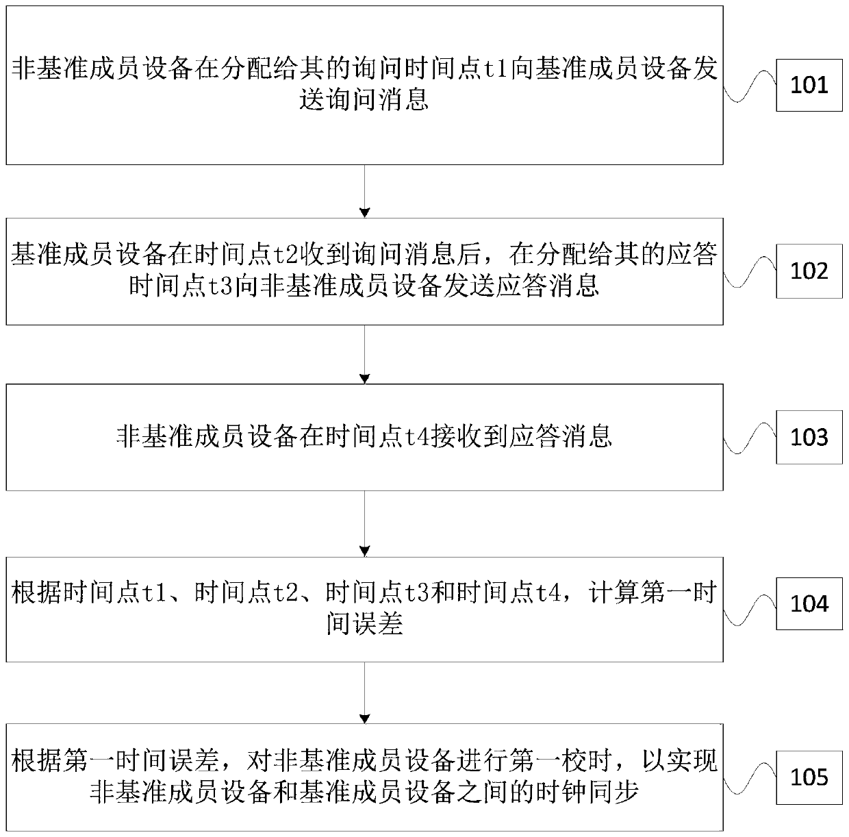
[0032] Please refer to figure 1 , this embodiment provides a system clock synchronization method for clock synchronization between non-reference member devices and reference member devices in the system, including:
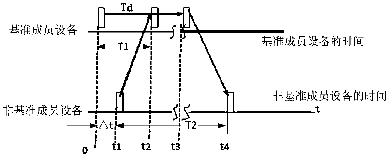
[0033] Step 101, the non-reference member device sends an inquiry message to the reference member device at the assigned inquiry time point t1;
[0034] Step 102: After receiving the inquiry message at time point t2, the reference member device sends a response message to the non-reference member device at the response time point t3 assigned to it;
[0035] Step 103, the non-reference member device receives the response message at time point t4;
[0036] Step 104, according to time point t1, time point t2, time point t3 and time point t4, calculate the first time error Δt1;
[0037] Step 105: Perform a first time calibration on the non-reference member device according to the first time error Δt1, so as to realize clock synchronization between the non-reference ...
Embodiment 2
[0044] Since each non-reference member device in the system generally only performs time calibration once in its corresponding first time calibration period, its timing accuracy is poor, so this embodiment also includes on the basis of Embodiment 1:
[0045] Build a time calibration model according to the time error and the preset time calibration period T1;
[0046] According to the timing model, the second time error Δt2 is obtained;
[0047] According to the second time error Δt2, the second time comparison is performed on the non-reference member device after the end time T2 of the first time correction.
[0048] In this embodiment, the timing model is as formula two:
[0049] Δt2=kt+T Formula 2
[0050] Wherein, t is the first time calibration period of the non-reference member device, k is the clock drift per unit time, and T is the delay time.
specific Embodiment approach
[0051] In a specific implementation manner, the first time calibration period is 200-300ms.
[0052] The delay time T is the sum of the system transmit channel delay time, receive channel delay time and pseudo-code synchronization pulse delay time. The above-mentioned delay time is basically a fixed value when the hardware design is consistent, and the delay time T can be obtained by measuring multiple samples and probabilistic statistical analysis.
[0053] For example, the transmit channel delay time can be passed image 3 According to the method shown, the radio frequency signal is generated by the radio frequency signal generator, and the radio frequency signal is coupled and detected by the radio frequency signal after passing through the transmission channel, and then the delay time of the transmission channel is obtained by starting / stopping the timer.
[0054] The receiving channel delay time can be passed Figure 4 The method shown is to obtain it, which generates a...
PUM
 Abstract
Description
Claims
Application Information
 - R&D
- Intellectual Property
- Life Sciences
- Materials
- Tech Scout
- Unparalleled Data Quality
- Higher Quality Content
- 60% Fewer Hallucinations
Browse by: Latest US Patents, China's latest patents, Technical Efficacy Thesaurus, Application Domain, Technology Topic, Popular Technical Reports.
© 2025 PatSnap. All rights reserved.Legal|Privacy policy|Modern Slavery Act Transparency Statement|Sitemap|About US| Contact US: help@patsnap.com


