Low-power consumption precise timer and its precision correcting equipment, system and method

A technology for correcting equipment and time correction, applied to electronic timers, integrated device timers, radio-controlled timers, etc., can solve the problems of high cost and bulky timing devices, and achieve simple data exchange and transmission processes quick effect

Inactive Publication Date: 2003-06-04
ZHUHAI PRECISION ELECTRONICS
View PDF1 Cites 15 Cited by
  • Summary
  • Abstract
  • Description
  • Claims
  • Application Information

AI Technical Summary

Problems solved by technology

But if the signal of GPS, SPS or radio system is used directly to correct or correct the time, it is unavoidable to set up a signal rece...

Method used


Image

  • Low-power consumption precise timer and its precision correcting equipment, system and method
  • Low-power consumption precise timer and its precision correcting equipment, system and method
  • Low-power consumption precise timer and its precision correcting equipment, system and method

Examples


Embodiment Construction

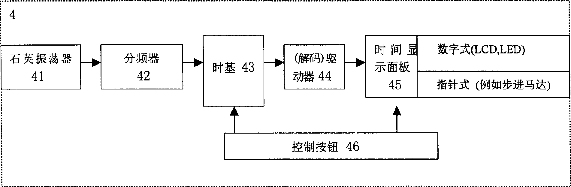
[0054] like figure 1 As shown, the traditional electronic timing device 4 generally includes basic operation blocks such as a quartz oscillator 41 , a frequency divider 42 , a time base 43 , a driver 44 , a time display panel 45 , and control buttons 46 . The core part is usually a quartz oscillator 41, and the oscillation frequency of the quartz oscillator circuit in it is about 2 n Hz, typically 32.767kHz (2 15 ) ~ 4.194304MHz (2 22 )between. After the quartz oscillator frequency is distributed by the frequency divider 42, a 1 Hz signal can be obtained and a time base signal can be generated respectively. The time base signal is stored in the time base 43, generates time after being decoded by the driver 44, and the time is displayed on the time display panel 45, and the means of display include LCD, LED display or similar means (such as a pointer type display driven by a stepping motor) means). In general, frequency distribution, time base conversion (decoding), time d...


PUM


Abstract

The present invention is one electronic timer and time correcting equipment, system and method. The electronic timer includes simple and low-power consumption error correcting circuit for raising time accuracy. The error correcting data are calculated by outer equipment based on the data the electronic timer produces, the stored data and outer standard time data, and is stored in the memory of the electronic timer. Thus, the microprocessor of the electronic timer can correct time without needing great amount of calculation.

Description

technical field [0001] The present invention relates to a timing device and a device, system and method for correcting its accuracy, in particular to a low power consumption precise electronic timing device and its timing can be corrected and updated by applying the time signal of GPS, SPS or radio system Precision devices, systems and methods. Background technique [0002] Nowadays, electronic timekeeping products such as digital watches are widely used due to reasons such as accurate timekeeping and low maintenance costs. Electronic timing products usually include an electronic oscillator and a controller. The oscillator generally contains a frequency of about 32.768kHz (2 15 kHz) ~ 4.194304MHz (2 22 MHz) quartz oscillators, the controller usually includes a microprocessor to count the number of oscillation pulses and convert them into time for display. These electronic timekeeping devices are generally considered to be more accurate, but in fact they deviate significan...

Claims


Application Information

Patent Timeline
IPC IPC(8): G04G21/00G04R20/06G04R40/06
Inventor 陈笠
Owner ZHUHAI PRECISION ELECTRONICS
Why Eureka
Try Eureka