
Pipe penetrating device for electronic wire harness machining

A pipe threading device and electronic wire technology, applied in the direction of cable laying equipment, etc., can solve the problems of poor pipe threading effect, affect pipe threading efficiency, reduce pipe threading efficiency, etc., achieve good pipe threading effect and improve pipe threading efficiency Effect

Active Publication Date: 2020-09-18
SHENZHEN TRONIXIN ELECTRONICS
View PDF14 Cites 5 Cited by
  • Summary
  • Abstract
  • Description
  • Claims
  • Application Information

AI Technical Summary

Problems solved by technology

[0005] The technical problem to be solved by the present invention is to provide a pipe threading device for electronic wire harness processing, to solve the problem that the device in the prior art cannot ensure that the wire harness is straight and the wire harness is bent during the process of unwinding, resulting in poor pipe threading effect. Reduce the efficiency of pipe threading, and do not deal with the wire harnesses that have been threaded through the pipes. A large number of threaded wire harnesses are pushed and accumulated on the device, which may cause problems between the threaded wire harness tubes and affect the pipe threading efficiency.

Method used

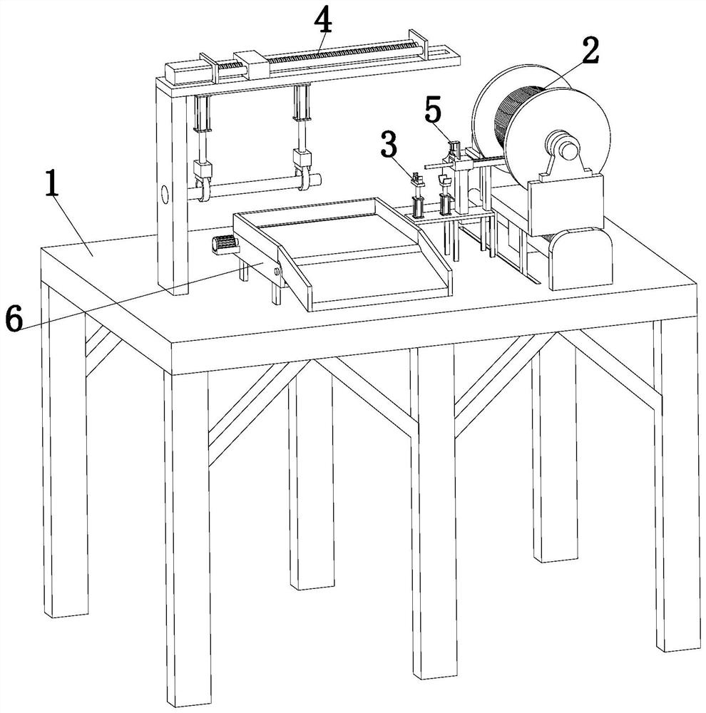
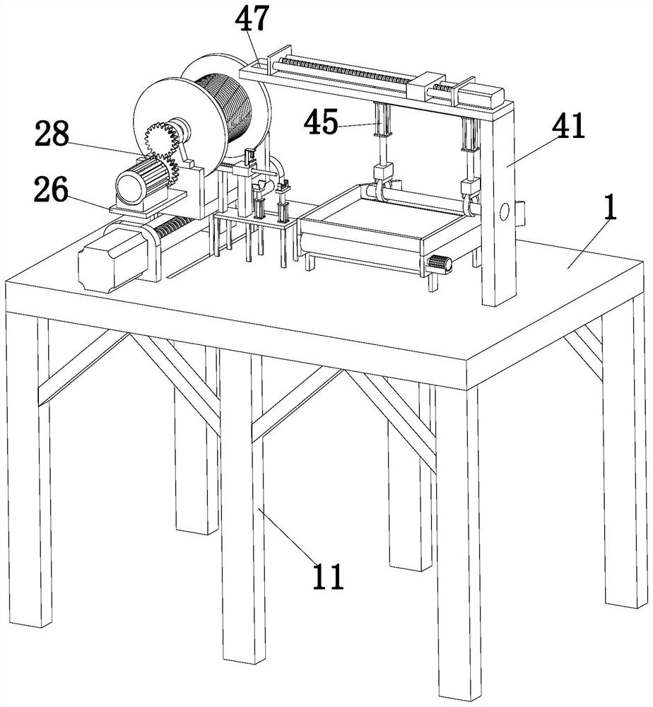
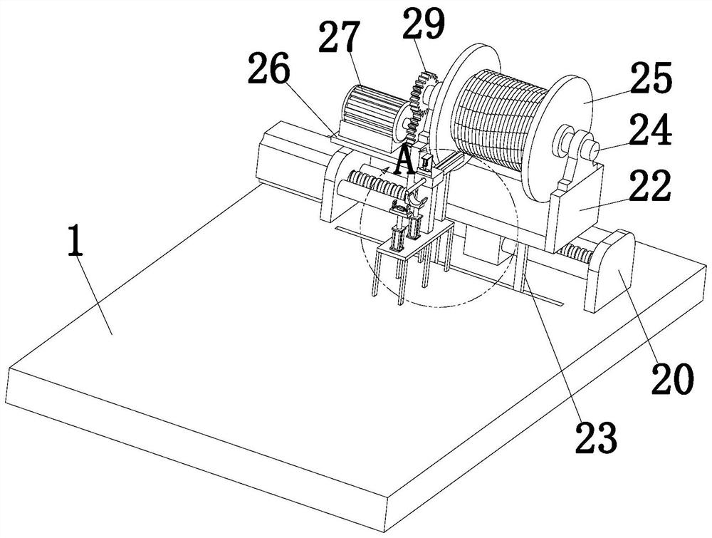

Image

  • Pipe penetrating device for electronic wire harness machining
  • Pipe penetrating device for electronic wire harness machining
  • Pipe penetrating device for electronic wire harness machining

Examples


Embodiment Construction

[0024] In order to make the object, technical solution and advantages of the present invention clearer, the present invention will be further described in detail below in conjunction with the accompanying drawings and embodiments. It should be understood that the specific embodiments described here are only used to explain the present invention, not to limit the present invention.

[0025] In describing the present invention, it should be understood that the terms "longitudinal", "transverse", "upper", "lower", "front", "rear", "left", "right", "vertical", The orientations or positional relationships indicated by "horizontal", "top", "bottom", "inner", "outer", etc. are based on the orientations or positional relationships shown in the drawings, and are only for the convenience of describing the present invention, rather than indicating or It should not be construed as limiting the invention by implying that a referenced device or element must have a particular orientation, be...


PUM


Abstract

The invention relates to the technical field of automobile electronic machinery, in particular to a pipe penetrating device for electronic wire harness machining. The device comprises a workbench, a pay-off device, a positioning device, a pipe penetrating device, a wire cutting device and a conveying device. A sliding groove matched with the pay-off device is formed in the top of the workbench. The pay-off device is arranged at the top of the workbench and is in sliding fit with the sliding groove. The positioning device is arranged on the workbench and located beside the pay-off device. The pipe penetrating device is arranged at the top of the workbench, and the pipe penetrating device and the pay-off device are located on the same horizontal plane. The wire cutting device is arranged onthe positioning device, and the output end of the wire cutting device is vertically downward; the conveying device is arranged below the pipe penetrating device and fixed to the workbench. The pay-offdevice is used for paying off, the positioning device is used for assisting and effectively enabling the paid-off wire harness to be straight, the pipe penetrating efficiency is improved, the penetrated pipe is conveyed away by the conveying device, and the influence on the pipe penetrating effect of the wire harness due to accumulation of a large number of penetrated wire harness pipes on the processing device is prevented.

Description

technical field [0001] The invention relates to the technical field of automobile electronic machinery, in particular to a pipe threading device for electronic wire harness processing. Background technique [0002] With the development of the economy and the improvement of people's living standards, more and more families buy cars, which affects the rapid development of the automotive industry. In automotive electronic devices, electronic wiring harnesses are needed. Electronic wiring harnesses are punched by copper materials. After crimping the contact terminal (connector) and the wire and cable, the outer surface is re-molded with an insulator or an additional metal shell, etc., and the wiring harness is bundled to form a component connecting the circuit to prevent the electronic wiring harness from being damaged. Usually, it is necessary to wrap the wiring harness into a hose to protect the electronic wiring harness. [0003] For example, the patent with the publication ...

Claims


Application Information

Patent Timeline
Patent Type & Authority Applications(China)
IPC IPC(8): H02G1/08
CPCH02G1/08
Inventor 朱昀
Owner SHENZHEN TRONIXIN ELECTRONICS
Learn More