
Eureka
For R&D, Eureka makes reading and utilizing patents & technical documents easy.
Eureka AIR
Designed for self-driven R&D workflows. Generate viable solutions, solve complex R&D challenges, empower your innovation with AI.

Eureka Materials
Designed for material experts only. Revolutionize your material R&D, from search, analyze, to developing new materials.

TechResearch
Generate reliable direction feasibility study reports for your R&D in just a few steps.

TechSeek
Discover and master advanced knowledge NOW. Basics, ideas, possibilities, all at once.

TechMind
As an expert in R&D Theories, TechMind can generates customized viable solutions instantly.

TechRisk
Analyze your overall solution with one click, know your potential R&D risks in advance.

TechMonitor
Get weekly tech updates, stay abreast of the latest tech innovations and key insights.
A rapid cooling and cooling device for billiards casting
A rapid cooling and cooling device technology, applied in applications, household appliances, household components, etc., can solve the problems of reduced processing efficiency, long cooling time, reduced billiards and molds, etc., to reduce the direct impact and reduce the temperature effect.
- Summary
- Abstract
- Description
- Claims
- Application Information
AI Technical Summary
Problems solved by technology
Method used
Image

Examples
Embodiment 1
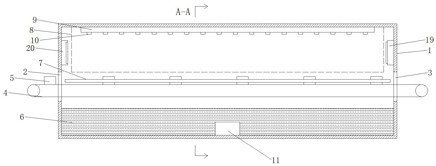
[0021] Please refer to the figure, in the embodiment of the present invention, a rapid cooling and cooling device for casting billiard balls includes a housing 1, a material inlet 2, a material outlet 3 and a conveyor belt 4; the housing 1 is a box structure arranged horizontally. The left and right ends of the casing 1 are provided with a feed port 2 and a discharge port 3 in the same horizontal direction, and a conveyor belt 4 is horizontally arranged in the casing 1, and the left and right ends of the conveyor belt 4 are connected from the feed port 2 and the discharge port respectively. The material port 3 passes through, and the two ends of the conveyor belt 4 are driven by the transmission rollers, so that the conveyor belt 4 transports the billiard ball mold 5 placed thereon to the shell 1, so that the billiard ball mold 5 is cooled in the shell 1.
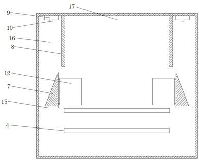
[0022] Two vertical and parallel water baffles 8 are fixed inside the housing 1, and the water baffles 8 are arranged symm...
Embodiment 2
[0026] On the basis of embodiment 1, blower 19 and suction fan 20 are respectively arranged on the two ends of the housing 1 corresponding to the blowing cooling cavity 17, and blower 19 is located above the discharge port 3, and the suction fan 20 is located at the feed port 2 Above, make the air flow direction in the blowing cooling chamber 17 and the moving direction below the billiard ball mold 5 inside, realize the cooling and cooling of the billiard ball mold 5 by the internal blowing.
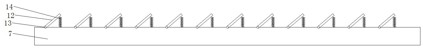
[0027] During use, the poured billiard ball mold 5 is placed on the conveyor belt 4, and each billiard ball mold 5 corresponds to each convex line 18 on the conveyor belt 4, so as to avoid slipping between the billiard ball mold 5 and the conveyor belt 4, and the billiard ball mold 5 passes through the conveyor belt 4. Feed into the shell 1 from the feed port 2; the billiard ball mold 5 enters the shell 1 and is located under the blowing cooling chamber 17, and takes away part of the heat...
PUM
 Abstract
Description
Claims
Application Information
 - R&D Engineer
- R&D Manager
- IP Professional
- Industry Leading Data Capabilities
- Powerful AI technology
- Patent DNA Extraction
Browse by: Latest US Patents, China's latest patents, Technical Efficacy Thesaurus, Application Domain, Technology Topic, Popular Technical Reports.
© 2024 PatSnap. All rights reserved.Legal|Privacy policy|Modern Slavery Act Transparency Statement|Sitemap|About US| Contact US: help@patsnap.com