Logic supporting structure and anti-collision device of offshore structure

A technology of marine structure and anti-collision device, applied in the field of marine and ships, can solve the problems of metal foam plastic damage, low rigidity, deformation damage, etc., and achieve the effect of reducing reaction force and impact contact force

Active Publication Date: 2020-09-22
OCEAN UNIV OF CHINA
View PDF4 Cites 0 Cited by
  • Summary
  • Abstract
  • Description
  • Claims
  • Application Information

AI Technical Summary

Problems solved by technology

[0003] In the traditional anti-collision method, the air bag, viscoelastic material (rubber), metal foam, etc. are introduced into the protected structure (such as offshore wind turbine) (such as figure 1 As shown), the above structure can reduce the impact contact force, but its stiffness is very low. Under normal working conditions (such as berthing a ship), this type of low stiffness material (structure) will also produce large deformation, and the metal foam may also undergo plastic failure. , large waves, etc. may also cause large deformation or even damage to these low-stiffness materials (structures)

Method used


Image

  • Logic supporting structure and anti-collision device of offshore structure
  • Logic supporting structure and anti-collision device of offshore structure
  • Logic supporting structure and anti-collision device of offshore structure

Examples


Embodiment 1

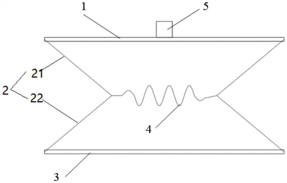
[0042] see figure 2 , the present application is a logical support structure for offshore structures, including a bearing part 1, a fixing part 3, a brace 2 and a linear spring 4; the bearing part 1 and the fixing part 3 are arranged in parallel; the brace 2 includes a first The diagonal brace 21 and the second diagonal brace 22, the first diagonal brace 21 and the second diagonal brace 22 are all arranged in pairs, and one end of the two first diagonal braces 21 is respectively hinged at the two ends of the bearing part, and the other end faces the opposite direction. The direction is inclined, and one end of the two second diagonal braces 22 is respectively hinged on the two ends of the fixed portion, and the other end is inclined in the opposite direction, and the other end is respectively hinged with the other end of the corresponding first diagonal brace; the linear The spring 4 is arranged between the bearing part and the fixing part, and its two ends are respectively h...

Embodiment 2

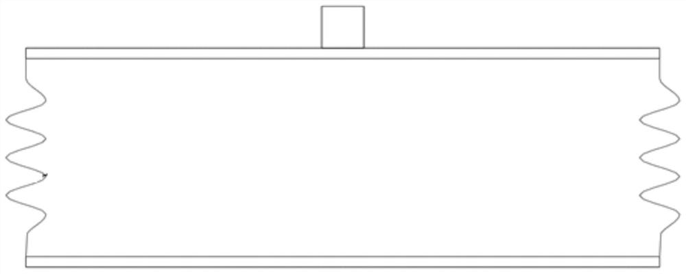
[0048] see Image 6 with Figure 7 , further, the present application also provides an anti-collision device 6 for offshore structures, including a load-bearing part 1, a fixed part 3 and a spring system, the load-bearing part 1 and the fixed part 3 are arranged in parallel, and the spring system includes multiple sets of consecutively arranged spring unit, each spring unit includes a brace 2 and a linear spring 4, the brace 2 includes a first brace 21 and a second brace 22, the first brace 21 and the second brace 22 are formed For the setting, one end of the two first diagonal braces 21 is hinged on the bearing part 1 at intervals, and the other end is inclined in the opposite direction, and one end of the two second diagonal braces 22 is hinged on the fixed part at intervals, and the other end faces the opposite direction. The direction is inclined, the other end of which is respectively hinged with the other end of the corresponding first diagonal brace 21; The intersecti...

Embodiment 3

[0089] see Figure 8 ~ Figure 10 , the present application also provides an anti-collision structure for offshore wind turbines, including the wind turbine and an anti-collision device 6, the anti-collision device 6 adopts the logical anti-collision device described in Embodiment 2, the anti-collision device is vertically arranged, and its The fixing part is fixed on the outer periphery of the wind turbine tower 7 .

[0090] Specifically, the anti-collision device is vertically arranged at the position where the wind turbine tower 7 is close to the sea surface, and acts on the bearing part 1 of the anti-collision device when the ship 8 docks or collides normally.


PUM


Abstract

The invention discloses a logistic supporting structure and an anti-collision device for an offshore structure. The logistic supporting structure comprises a bearing part, a fixing part, inclined struts, and a linear spring; the bearing part and the fixing part are arranged in parallel; the inclined struts comprise first inclined struts and second inclined struts, the first inclined struts and thesecond inclined struts are respectively arranged in pairs, one ends of the two first inclined struts are hinged to the two ends of the bearing part correspondingly, the other ends of the two first inclined struts incline in the opposite direction, one ends of the two second inclined struts are hinged to the two ends of the fixing part correspondingly, the other ends of the two second inclined struts incline in the opposite direction, and the other ends of the two second inclined struts are hinged to the other ends of the corresponding first inclined struts; and the linear spring is arranged between the bearing part and the fixing part, and the two ends of the linear spring are hinged to the intersection points of the first inclined struts and the second inclined struts respectively. The supporting structure has high rigidity in the initial state, when the bearing capacity of the supporting structure reaches a certain threshold value, the structural rigidity is reduced, implementationof normal operation can be ensured, and the impact contact force can be reduced under the impact working condition.

Description

technical field [0001] The invention relates to the technical field of marine and ships, in particular to a logical support structure and anti-collision device for offshore structures. Background technique [0002] Marine and marine engineering structures may be subjected to short-term strong loads such as collisions with out-of-control ships. Effective anti-collision has become a major requirement to ensure the safety of marine engineering structures. [0003] In the traditional anti-collision method, the air bag, viscoelastic material (rubber), metal foam, etc. are introduced into the protected structure (such as offshore wind turbine) (such as figure 1 As shown), the above structure can reduce the impact contact force, but its stiffness is very low. Under normal working conditions (such as berthing a ship), this type of low stiffness material (structure) will also produce large deformation, and the metal foam may also undergo plastic failure. , large waves, etc. may also...

Claims


Application Information

Patent Timeline
Patent Type & Authority Applications(China)
IPC IPC(8): B63B43/18
CPCB63B43/18
Inventor 方辉孟祥剑李德鉴段利亚李华军刘勇
Owner OCEAN UNIV OF CHINA
Why Eureka
Try Eureka