Fan blade adjusting water draining flow limiting device

A technology of flow limiting device and fan blade, which is applied in the direction of valve device, valve operation/release device, valve details, etc., and can solve the problem that the one-way displacement cannot be adjusted.

Inactive Publication Date: 2020-09-25
王学红
View PDF5 Cites 1 Cited by
  • Summary
  • Abstract
  • Description
  • Claims
  • Application Information

AI Technical Summary

Problems solved by technology

[0004] The purpose of the present invention is to solve the problem that only one-way drainage can be completed, and the amount of one-way drainage cannot be adjusted, and a fan blade adjustment drainage flow limiting device is proposed

Method used


Image

  • Fan blade adjusting water draining flow limiting device
  • Fan blade adjusting water draining flow limiting device
  • Fan blade adjusting water draining flow limiting device

Examples


Embodiment Construction

[0023] The following will clearly and completely describe the technical solutions in the embodiments of the present invention with reference to the accompanying drawings in the embodiments of the present invention. Obviously, the described embodiments are only some, not all, embodiments of the present invention.

[0024] In describing the present invention, it should be understood that the terms "upper", "lower", "front", "rear", "left", "right", "top", "bottom", "inner", " The orientation or positional relationship indicated by "outside", etc. is based on the orientation or positional relationship shown in the drawings, and is only for the convenience of describing the present invention and simplifying the description, rather than indicating or implying that the referred device or element must have a specific orientation, so as to Specific orientation configurations and operations, therefore, are not to be construed as limitations on the invention.

[0025] refer to Figure ...


PUM


Abstract

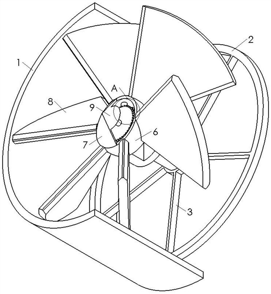
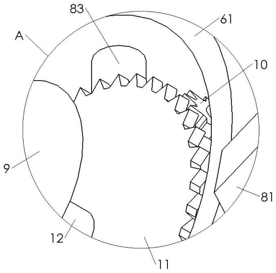
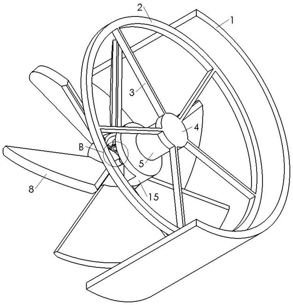
The invention discloses a fan blade adjusting water draining flow limiting device. The fan blade adjusting water draining flow limiting device comprises a pipeline, a supporting ring is fixedly connected to the inner wall of the pipeline, a supporting rotating device is arranged on the supporting ring, a rotating device is arranged in the pipeline, a connecting block is fixedly connected between the supporting rotating device and the rotating device, multiple rotating bodies rotate in rotating holes formed in the side wall of a rotating bottom ring, the angles between the rotating bodies and the end face of the rotating bottom ring can be effectively adjusted, due to the fact that that the rotating direction of an electric motor is not changed, the multiple rotating bodies can be regulatedby the corresponding angle, under driving of the electric motor, the adjusting of the flow direction of water in the pipeline can be finished, in necessity, the multiple rotating bodies can be adjusted to the same plane, the rotating bodies plug the opening diameter of the pipeline, seal strips are arranged on the side walls of the rotating bodies, the seal effect is achieved, and the water blocking effect is achieved.

Description

technical field [0001] The invention relates to the technical field of flow limiting devices, in particular to a fan blade regulating drainage flow limiting device. Background technique [0002] At present, in industrial production, it is often necessary to connect two reservoirs with pipes, to transfer and exchange the liquid in the two reservoirs, and to raise the water level of one of the reservoirs. These operations require a series of complicated devices. For operation, these devices can only complete one-way drainage, and the amount of one-way drainage cannot be adjusted; when the liquid delivery exchange is completed, the delivery needs to be interrupted, and other equipment needs to be used to close the pipeline, which greatly increases the difficulty of operation; when When two-way water exchange is required, the existing device is too bulky and complicated to operate, and the effect achieved is not ideal. [0003] For this reason, we have designed a kind of fan bl...

Claims


Application Information

Patent Timeline
Patent Type & Authority Applications(China)
IPC IPC(8): F16K1/22F16K1/226F16K31/04F16K31/53
CPCF16K1/222F16K1/223F16K1/225F16K1/2261F16K31/043F16K31/535
Inventor 王学红
Owner 王学红
Why Eureka
Try Eureka