
A leak-proof breathing valve

A technology of anti-leakage and breathing valve, which is applied in the field of breathing valve, can solve the problems that the breathing valve cannot bear the oil pressure, leakage, and the anti-leakage technology cannot be satisfied, etc., and achieve the effect of convenient reset and simple reset structure

Active Publication Date: 2022-01-28
杭州萧山技师学院
View PDF7 Cites 0 Cited by
  • Summary
  • Abstract
  • Description
  • Claims
  • Application Information

AI Technical Summary

Problems solved by technology

[0005] When the oil tank is dumped, the breathing valve will leak because it cannot withstand the oil pressure, so the breathing valve needs to be sealed; the existing technology is to install a copper semicircular weight at the bottom of the valve. Under normal circumstances, the copper semicircular weight It is located at the bottom of the valve; when it is tipped, the weight will flip and seal the valve port under the action of weight; however, this technology is suitable for the situation where the oil tank is tipped over at a large angle, generally greater than 30 degrees; for small-angle tipping that occurs in reality Risks, such as when a fully loaded oil tanker goes up and down a slope or a side slope tipping angle is greater than 20 degrees but less than 30 degrees, and when a stationary oil-filled oil tank on the ground collapses after the ground collapses, the existing The anti-leakage technology cannot meet the anti-leakage requirements in this state, so it is necessary to design a breathing valve that can seal and not leak when tilted at a small angle

Method used


Image

  • A leak-proof breathing valve
  • A leak-proof breathing valve
  • A leak-proof breathing valve

Examples


Embodiment Construction

[0039] The specific implementation manners of the present invention will be further described in detail below in conjunction with the accompanying drawings and embodiments. The following examples or drawings are used to illustrate the present invention, but not to limit the scope of the present invention.

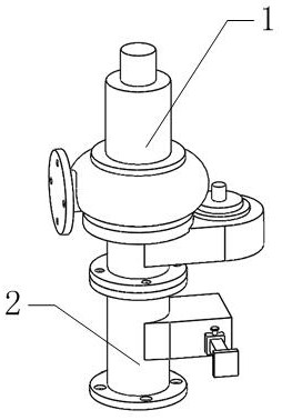
[0040] Such as figure 1 As shown, it includes a breather valve body 1, and the breather valve body 1 designed by the present invention has the same structure and function as the existing breather valve; The positive and negative pressure of oil and gas in the cargo storage tank can be automatically opened and closed to keep the pressure difference between the inside and outside of the storage tank within the allowable range. It is characterized in that it also includes an anti-leakage mechanism 2 .

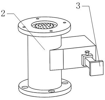
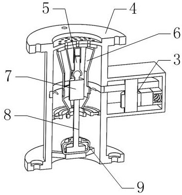
[0041] Such as figure 2 , 3 As shown, the anti-leakage mechanism includes a reset mechanism 3, an installation sleeve 4, a sealing plate 24, and a frame body 6, wherein th...


PUM


Abstract

The invention belongs to the technical field of breathing valves, and in particular relates to a leak-proof breathing valve, which includes a breathing valve body. The breathing valve designed in the present invention can be used only when the oil tank is tilted to more than 20 degrees. The structure composed of the installation base will fall down, driving the frame body and the sealing plate to swing, so that the second air hole opened on the sealing plate and the first air hole opened on the sealing cover are misaligned one by one, so that the installation sleeve and the breathing valve The channel between the bodies is closed to prevent leakage; when the inclination angle of the oil tank is less than 20 degrees, because the installation base is larger than the projected area of ​​the counterweight and the installation rod on the installation base, the counterweight and installation rod The structure formed with the mounting base will not fall over. The breather valve designed by the present invention, when the anti-leakage mechanism is not needed, press the rack, and then the gear is locked through the locking bolt, the second lock hole opened on the rack and the first lock hole opened on the guide sleeve. The strip is fixed on the mounting shell.

Description

[0001] Technical field [0002] The invention belongs to the technical field of breathing valves, in particular to a leak-proof breathing valve. Background technique [0003] The breathing valve is composed of a pressure valve and a vacuum valve. It is installed on the vent pipe of the storage tank. It can automatically open and close with the change of the positive and negative pressure of the oil and gas in the storage tank, so as to keep the pressure difference between the inside and outside of the storage tank within the allowable range. [0004] The breathing valve is a safe and energy-saving product that maintains the air pressure balance of the storage tank and reduces the volatilization of the medium. The breathing valve makes full use of the pressure bearing capacity of the storage tank itself to reduce the discharge of the medium. The principle is to use the weight of the positive and negative pressure valve disc to control the discharge of the storage tank. Inspirat...

Claims


Application Information

Patent Timeline
Patent Type & Authority Patents(China)
IPC IPC(8): F16K17/36F16K5/06F16K17/19
CPCF16K17/363F16K5/0605F16K5/061F16K5/0647F16K17/19
Inventor 王尧林徐顺和诸悦吴海明孙莹
Owner 杭州萧山技师学院
Learn More