High-speed puncture sampling system

A sampling system and high-speed technology, applied in the field of medical equipment, can solve problems such as rising failure rate, rising use cost, and easy wear and tear of equipment

Pending Publication Date: 2020-09-25
URIT MEDICAL ELECTRONICS CO LTD
View PDF0 Cites 0 Cited by
  • Summary
  • Abstract
  • Description
  • Claims
  • Application Information

AI Technical Summary

Problems solved by technology

[0003] The purpose of the present invention is to provide a high-speed puncture sampling system, which aims to solve the problems of the existing equi

Method used


Image

  • High-speed puncture sampling system
  • High-speed puncture sampling system
  • High-speed puncture sampling system

Examples


Embodiment Construction

[0020] Embodiments of the present invention are described in detail below, examples of which are shown in the drawings, wherein the same or similar reference numerals designate the same or similar elements or elements having the same or similar functions throughout. The embodiments described below by referring to the figures are exemplary and are intended to explain the present invention and should not be construed as limiting the present invention.

[0021] In describing the present invention, it should be understood that the terms "length", "width", "upper", "lower", "front", "rear", "left", "right", "vertical", The orientation or positional relationship indicated by "horizontal", "top", "bottom", "inner", "outer", etc. are based on the orientation or positional relationship shown in the drawings, and are only for the convenience of describing the present invention and simplifying the description, rather than Nothing indicating or implying that a referenced device or element...


PUM


Abstract

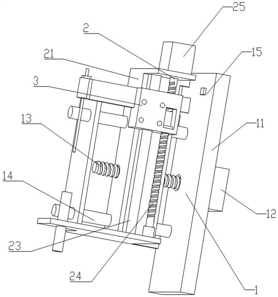
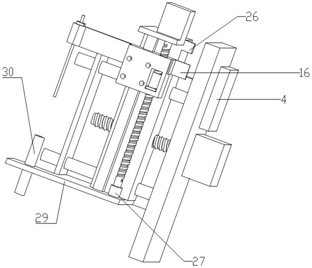
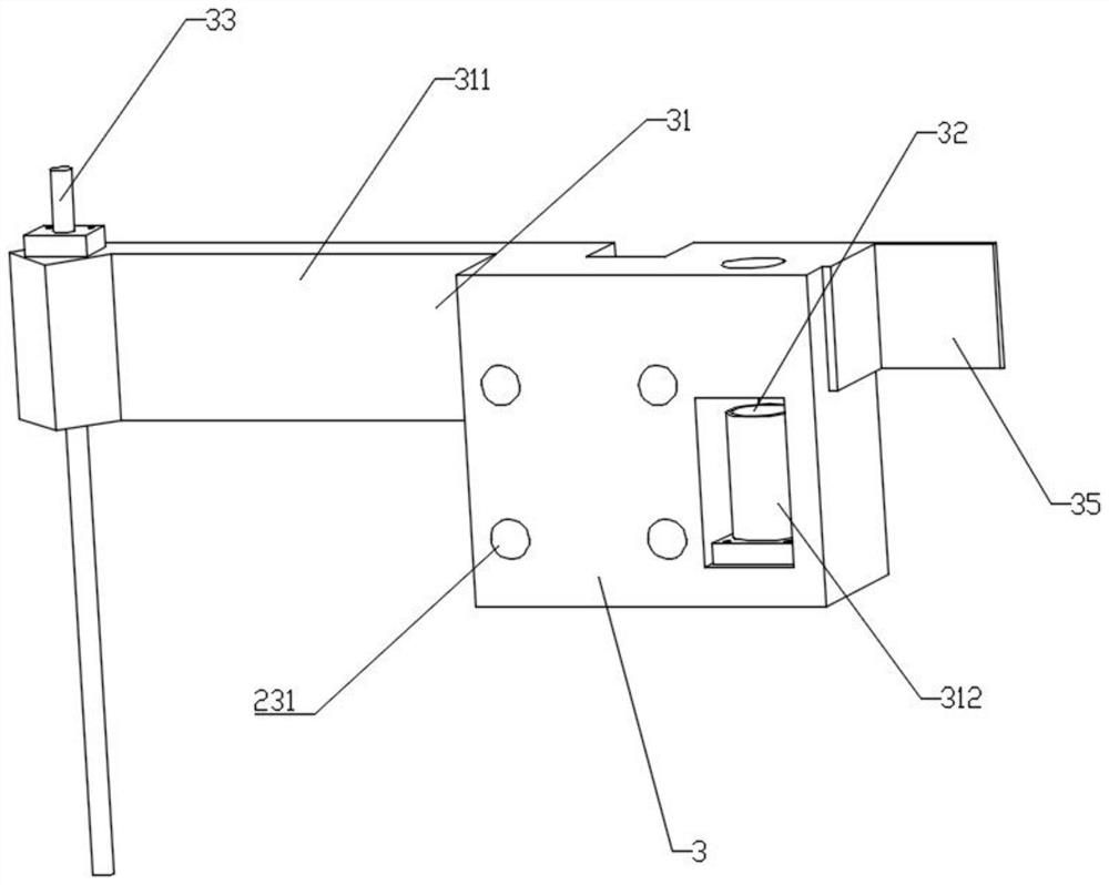
The invention discloses a high-speed puncture sampling system comprising a transverse movement assembly, a longitudinal movement assembly, a sampling assembly and a motor controller. A transverse motor moving transversely is connected with a supporting column, a transverse lead screw is connected with the transverse motor, and a longitudinal supporting seat of the longitudinal movement assembly isin threaded connection with the transverse lead screw through a transverse nut, so that the transverse motor can drive the longitudinal supporting seat to move; a longitudinal motor is connected withthe longitudinal supporting seat, a longitudinal lead screw is connected with the motor, and a guide rail is connected with the longitudinal supporting seat and located on one side of the longitudinal lead screw. A sampling arm of the sampling assembly is in threaded connection with a longitudinal screw rod through a longitudinal nut and is in sliding connection with the guide rail, so that the longitudinal motor can control the sampling arm to move up and down, and a sampling needle on the sampling arm is controlled to sample. The number of structural parts is greatly reduced by being compared with the prior art, the structure is simple, and maintenance is convenient.

Description

technical field [0001] The invention relates to the technical field of medical instruments, in particular to a high-speed puncture sampling system. Background technique [0002] At present, in the field of medical device testing, as the degree of automation becomes higher and higher, the requirements for sampling speed and stability are also higher and higher. Therefore, the moving mechanism integrated into the instrument to absorb liquid samples is becoming more and more complex and bulky. , for motion sampling devices, most generally use a guide rod plus a screw motor, and the two ends of the screw slider will have two radial forces in opposite directions relative to the main shaft. When the force output by the screw rod is greater, the radial force will also be greater. Large, so that the sliding part on the screw rod is inclined at a certain angle relative to the main shaft of the screw rod, and it is easy to cause uneven force on the bearing and guide rod, and it is eas...

Claims


Application Information

Patent Timeline
IPC IPC(8): G01N35/10
CPCG01N35/10G01N35/1081G01N2035/1027
Inventor 俞凯硕覃洪瞻李磊赵洪财韦守龙
Owner URIT MEDICAL ELECTRONICS CO LTD
Why Eureka
Try Eureka