

Laser printer powder bin self-weight powder coating equipment
A technology of laser printers and toner bins, applied in the fields of equipment, optics, and electrical recording technology using charge patterns, etc., which can solve printing failures, excessive blank paper, and unavoidable opening of the printer to add powder and other problems to achieve the effect of avoiding jamming and avoiding paper waste
- Summary
- Abstract
- Description
- Claims
- Application Information
AI Technical Summary
Problems solved by technology
Method used
Image

Examples
Embodiment Construction
[0020] The following will clearly and completely describe the technical solutions in the embodiments of the present invention with reference to the accompanying drawings in the embodiments of the present invention. Obviously, the described embodiments are only some, not all, embodiments of the present invention. Based on the embodiments of the present invention, all other embodiments obtained by persons of ordinary skill in the art without making creative efforts belong to the protection scope of the present invention.
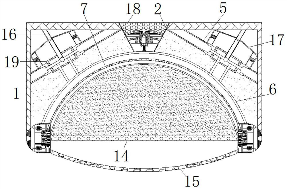
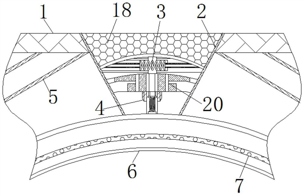
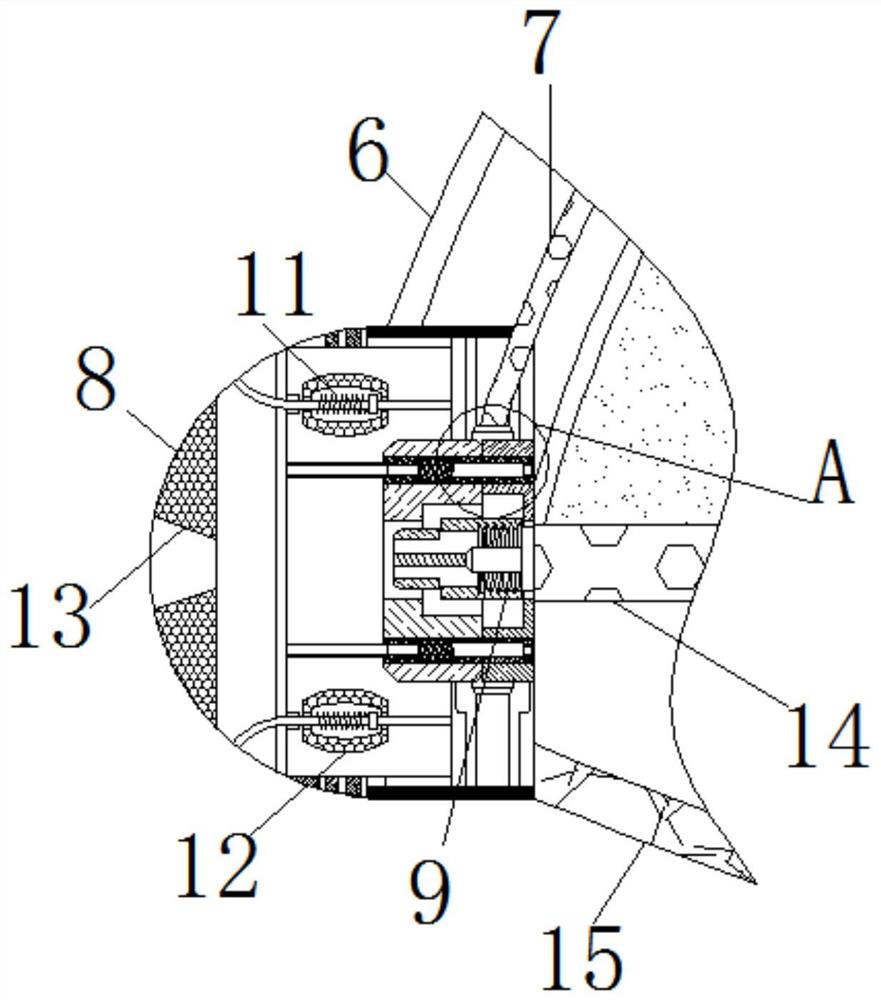
[0021] see Figure 1-4 , a self-weight powder coating device for a laser printer, comprising a housing 1, the housing 1 is provided with a placement slot 2, the inner top wall of the placement slot 2 is fixedly connected to an air bag 18, and the elastic force of the air bag 18 is smaller than that of the cushioning spring 3, the function of the airbag 18 is to increase the pressure difference, and then push the elastic plate 4 to apply a certain force on the ...
PUM
 Abstract
Description
Claims
Application Information