Rotor structure, motor and compressor

A technology of rotor structure and rotor iron core, which is applied in the direction of magnetic circuit shape/style/structure, electrical components, electromechanical devices, etc., and can solve the problems of high vibration and noise of the motor.

Pending Publication Date: 2020-09-25
ZHUHAI GREE REFRIGERATION TECH CENT OF ENERGY SAVING & ENVIRONMENTAL PROTECTION
View PDF0 Cites 0 Cited by
  • Summary
  • Abstract
  • Description
  • Claims
  • Application Information

AI Technical Summary

Problems solved by technology

[0005] The main purpose of the present invention is to provide a rotor structure, motor and compressor to solve the problem of relatively high vibration and noise of motors in the prior art

Method used


Image

  • Rotor structure, motor and compressor
  • Rotor structure, motor and compressor
  • Rotor structure, motor and compressor

Examples


Embodiment Construction

[0040] It should be noted that, in the case of no conflict, the embodiments in the present application and the features in the embodiments can be combined with each other. The present invention will be described in detail below with reference to the accompanying drawings and examples.

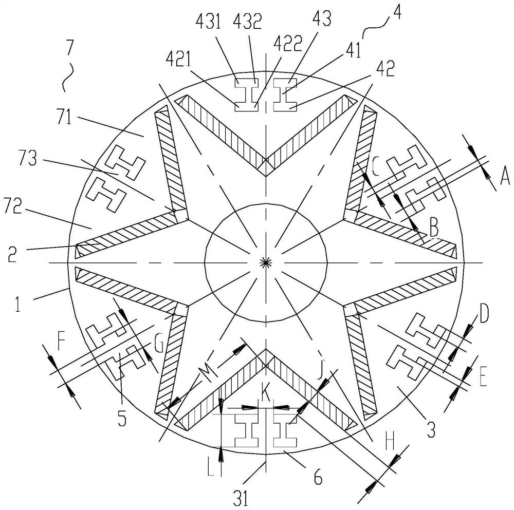
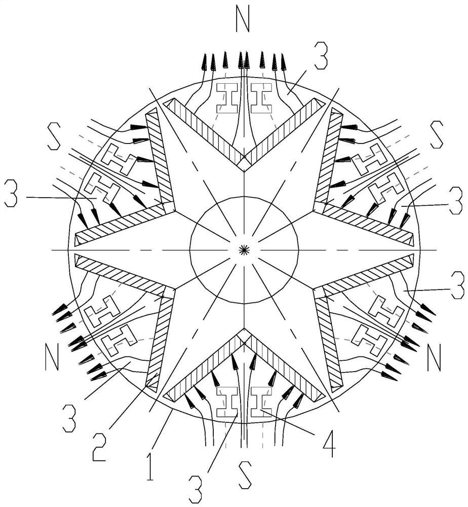
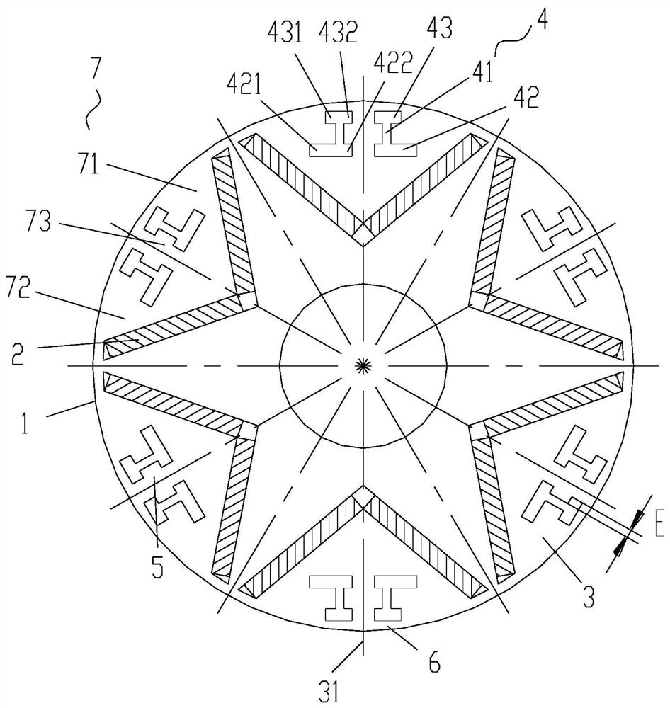
[0041] Such as Figure 1 to Figure 7 As shown, the present invention provides a rotor structure, including a rotor core 1 and a plurality of permanent magnets 2 arranged on the rotor core 1, so as to form a plurality of magnetic poles 3 on the rotor core 1, and the plurality of magnetic poles 3 include A plurality of N poles and a plurality of S poles arranged alternately along the circumferential direction of the rotor core 1; at least one magnetic pole 3 of the rotor core 1 is provided with a magnetic isolation hole 4, and the magnetic isolation hole 4 includes first holes communicating with each other 41, the second hole body portion 42 and the third hole body portion 43; the second hole bo...


PUM


Abstract

The invention mainly aims to provide a rotor structure, a motor and a compressor. The rotor structure comprises a rotor iron core and a plurality of permanent magnets arranged on the rotor iron core so as to form a plurality of magnetic poles on the rotor iron core, wherein the plurality of magnetic poles comprise a plurality of N poles and a plurality of S poles which are alternately arranged along the circumferential direction of the rotor iron core, at least one magnetic pole of the rotor iron core is provided with a magnetic isolation hole, the magnetic isolation hole comprises a first hole body part, a second hole body part and a third hole body part which are communicated with one another, the second hole body part and the third hole body part are respectively arranged at two ends ofthe first hole body part along the direction far away from the axis of the rotor iron core, and in the circumferential direction of the rotor iron core, the second hole body part and the third hole body part protrude out of the first hole body part. By means of the arrangement, the problem that in the prior art, vibration noise of a motor is large is solved.

Description

technical field [0001] The invention relates to the field of motors, in particular to a rotor structure, a motor and a compressor. Background technique [0002] In recent years, with the development of permanent magnet material manufacturing technology and rapid cost reduction, its excellent performance and low price have greatly promoted the development of permanent magnet motor technology. The abundant resources of permanent magnet materials have promoted the research and development of permanent magnet motor technology. [0003] Permanent magnet motors rely on permanent magnets to generate the main magnetic field. Compared with ordinary induction motors, permanent magnet synchronous motors do not require reactive excitation current, and the rotor resistance loss is zero under synchronous operation. Therefore, it has the characteristics of high power factor and high efficiency, and can usually be used to replace induction motors with low power indicators. Its economic and ...

Claims


Application Information

Patent Timeline
IPC IPC(8): H02K1/22H02K1/27
CPCH02K1/22H02K1/2766H02K2213/03
Inventor 王晶魏会军刘进超张辉周博陈华杰
Owner ZHUHAI GREE REFRIGERATION TECH CENT OF ENERGY SAVING & ENVIRONMENTAL PROTECTION
Why Eureka
Try Eureka