
Power supply charging and discharging management circuit, manager and management method

A charging and discharging management and power supply technology, applied in charging/discharging current/voltage regulation, battery circuit devices, different battery charging, etc., can solve problems such as low equipment utilization and complicated applications

Active Publication Date: 2020-09-25
无锡北方湖光光电有限公司
View PDF5 Cites 0 Cited by
  • Summary
  • Abstract
  • Description
  • Claims
  • Application Information

AI Technical Summary

Problems solved by technology

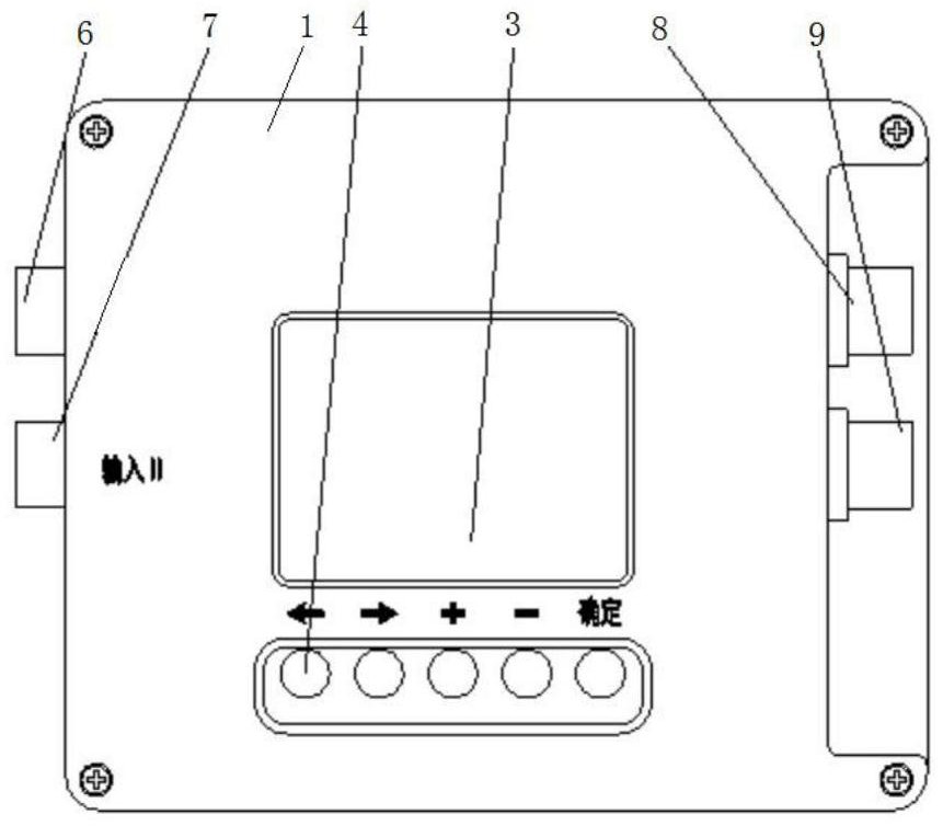
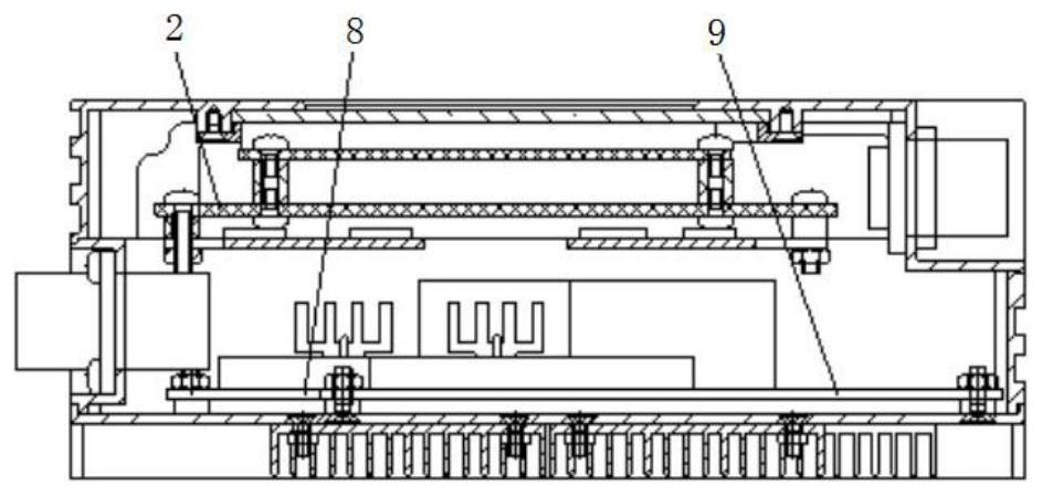
[0004] In the prior art, one kind of adapter corresponds to one type of electrical equipment, one type of charger corresponds to one type of battery, and one type of battery corresponds to one type of electrical equipment. The actual application is relatively complicated and the utilization rate of equipment is low. Problem, the purpose of the present invention is to provide a power supply charge and discharge management circuit, a manager and a management method, through which the power supply charge and discharge management circuit identifies the power supply device connected to the input end and automatically adapts, and automatically recognizes and adapts at the output end and selects the appropriate output The parameters automatically charge the connected battery or supply power to the electrical equipment, which greatly improves the scope of application and saves people from the trouble of matching the appropriate input power

Method used


Image

  • Power supply charging and discharging management circuit, manager and management method
  • Power supply charging and discharging management circuit, manager and management method
  • Power supply charging and discharging management circuit, manager and management method

Examples


Embodiment Construction

[0061] The technical solutions of the invention will be clearly and completely described below in conjunction with the accompanying drawings. Apparently, the described embodiments are part of the embodiments of the invention, not all of them. Based on the embodiments of the invention, all other embodiments obtained by persons of ordinary skill in the art without making creative efforts belong to the protection scope of the invention.

[0062] In the description of the invention, it should be noted that the terms "centre", "upper", "lower", "left", "right", "vertical", "horizontal", "inner", "outer", etc. indicate The orientation or positional relationship is based on the orientation or positional relationship shown in the drawings, which are only for the convenience of describing the invention and simplifying the description, rather than indicating or implying that the referred device or element must have a specific orientation, be configured in a specific orientation, and ope...


PUM


Abstract

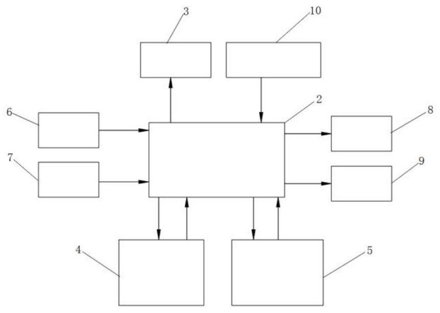
The invention discloses a power supply charging and discharging management circuit, a manager and a management method. The power supply charging and discharging management circuit is characterized bycomprising a main control board, an input end, a DC-DC direct-current power supply module, an output end, a key input module and a display circuit. The input end, the DC-DC direct current power supplymodule, the output end, the key input module and the display circuit are electrically connected with the main control board. The input end comprises a first input module and a second input module. The DC-DC power supply module comprises a first DC-DC power supply module and a second DC-DC power supply module, and the output end comprises a first output module and a second output module. The maincontrol board is connected with the input end, the DC-DC direct-current power supply module and the output end through multiple MOS switching tubes. The beneficial effects are that the power supply device accessed to the input end is identified and automatically adapted through the power supply charging and discharging management circuit, and the power supply device is automatically identified andadapted at the output end and selects appropriate output parameters to supply power to the accessed battery or electric equipment so that the application range can be enhanced.

Description

technical field [0001] The invention belongs to the technical field of power supply management, and in particular relates to a power supply charge and discharge management circuit, a manager and a management method with an input power intelligent self-adaptive function and an output voltage and current automatic selection function. Background technique [0002] With the development of the economy, the number and types of electrical equipment and batteries are increasing, and the number and types of corresponding power adapters and chargers are also increasing. In the prior art, there is usually a single correspondence between one type of adapter corresponding to one type of electrical equipment, one type of charger corresponding to one type of battery, and one type of battery corresponding to one type of electrical equipment. Low. Contents of the invention [0003] 1. Technical problems to be solved [0004] In the prior art, one kind of adapter corresponds to one type o...

Claims


Application Information

Patent Timeline
IPC IPC(8): H02M3/00H02M1/10H02J7/00H02J1/10
CPCH02M3/00H02M1/10H02J7/00032H02J7/00047H02J7/0013H02J7/007H02J7/0063H02J7/0047H02J1/10H02J1/102H02J2207/20H02M1/0083H02M1/009
Inventor 王宏斌杨怀东
Owner 无锡北方湖光光电有限公司
Learn More