Method for detecting and controlling solution viscosity of electronic atomization equipment and electronic atomization equipment

A technology of solution viscosity and electronic atomization, which is applied in the direction of tobacco, etc., can solve the problems of slow absorption and conduction, no smoke inhalation, and the difficulty of directly detecting the viscosity of the solution, so as to achieve a good user experience

Active Publication Date: 2020-09-29
HUIZHOU HAPPY VAPING TECH LTD
View PDF18 Cites 1 Cited by
  • Summary
  • Abstract
  • Description
  • Claims
  • Application Information

AI Technical Summary

Problems solved by technology

[0004] In the existing electronic atomization equipment, the solution to be atomized used by the atomizer has different fluidity at different viscosities. If the viscosity of the solution is high, the fluidity will become poor. The atomization unit of the atomizer The absorption and conduction of the solution become slow during work. If the electronic atomization device continues to atomize according to the original set procedure, and does not quickly increase the power to emit more heat to preheat the solution, it will easily lead to absorption. No smoke, giving users a bad taste and experience
[0005] In the existing detection and control method of solution viscosity of electronic atomization equipment, the solution to be atomized stored in the atomizer is generally a closed liquid storage chamber, and its space is narrow, so it is relatively difficult to directly detect the solution viscosity

Method used


Image

  • Method for detecting and controlling solution viscosity of electronic atomization equipment and electronic atomization equipment
  • Method for detecting and controlling solution viscosity of electronic atomization equipment and electronic atomization equipment
  • Method for detecting and controlling solution viscosity of electronic atomization equipment and electronic atomization equipment

Examples


Embodiment

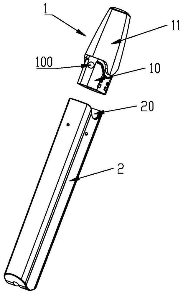
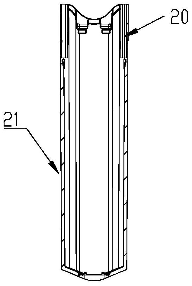
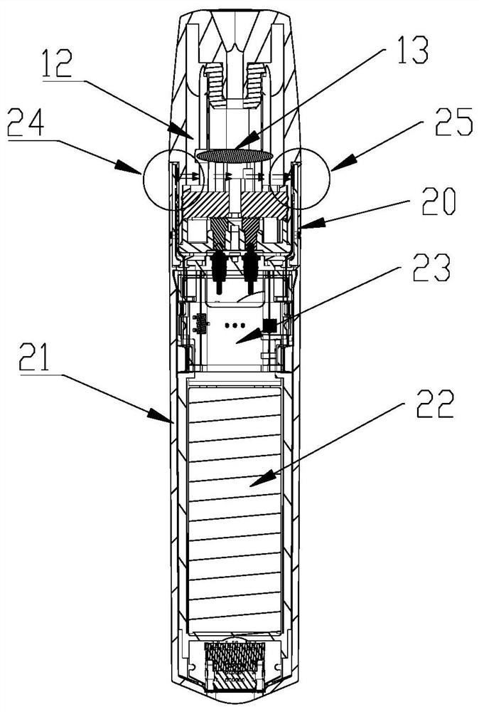
[0039] Such as Figure 1-Figure 4 As shown, the electronic atomization device used to implement the method of the present invention includes a detachably connected atomizer 1 and a power supply unit 2, the atomizer 1 includes a suction nozzle part 11 and a socket part 10, and the power supply unit 2 includes a The interface 20 through which the socket 10 is inserted and connected is accommodated, and the atomizer 1 is provided with a liquid storage chamber 12 and an atomizing unit 13 . The interface 20 is provided with a light source assembly 24 and a spectral sensor assembly 25, and the socket 10 is provided with a light-transmitting window 100 made of a light-transmitting material. The light emitted by the light source assembly 24 can pass through the light-transmitting window 100 and the solution to be atomized. Received by spectral sensor assembly 25. The solution 120 to be atomized is installed in the liquid storage chamber 12 , and the solution 120 to be atomized may be...


PUM


Abstract

The invention discloses an electronic atomization device solution viscosity detection and control method and an electronic atomization device thereof. The method comprises the steps that a light source assembly and a spectrum sensor assembly are arranged in an interface where an insertion part of an atomizer is inserted and connected into a power supply device; spectrum detection is carried out onthe sample solutions with different viscosities in the atomizer to obtain various calibration spectrum information, and the calibration spectrum information is written into a microcontroller arrangedin the power supply device; a corresponding relationship between the output power of the atomizer and the viscosity of the solution is preset; the light source assembly and the spectrum sensor assembly are connected with a power supply, and the spectrum sensor assembly performs spectrum detection on the to-be-atomized solution in the atomizer to obtain detection spectrum information; the microcontroller analyzes and compares the detection spectral information with various calibration spectral information, and if the detection spectral information is matched with one of the calibration spectral information, the microcontroller determines the detection viscosity of the to-be-atomized solution; and the output power of the atomizer is adjusted according to the detected viscosity and a presetfunction relationship between the output power and the solution viscosity.

Description

technical field [0001] The present invention relates to the technical field of electronic atomization equipment, and more specifically, the present invention relates to a method for detecting and controlling the viscosity of an electronic atomization equipment solution and the electronic atomization equipment thereof. Background technique [0002] Electronic atomization equipment includes electronic cigarettes, medical drug atomization equipment, etc., and its basic task is to provide a heating process to convert the liquid smoke or liquid medicine stored in the electronic atomization equipment into vapor mist, aerosol, steam or electronic cigarettes. smoke etc. [0003] Electronic atomization equipment generally includes a power supply unit and an atomizer. [0004] In the existing electronic atomization equipment, the solution to be atomized used by the atomizer has different fluidity at different viscosities. If the viscosity of the solution is high, the fluidity will be...

Claims


Application Information

Patent Timeline
Patent Type & Authority Applications(China)
IPC IPC(8): A24F40/40A24F40/51
CPCA24F40/40A24F40/51
Inventor 林光榕郑贤彬张夕勇
Owner HUIZHOU HAPPY VAPING TECH LTD
Why Eureka
Try Eureka