A slab root knocker for marble stone slab blanking
A technology for stone slabs and marble, which is applied in the field of slab root knockers for marble stone slab blanking, which can solve problems such as difficult to control the knocking force, accidental injury to staff, and crushing of stone slabs, so as to prevent crushing of staff Effect
- Summary
- Abstract
- Description
- Claims
- Application Information
AI Technical Summary
Problems solved by technology
Method used
Image

Examples
Embodiment 1
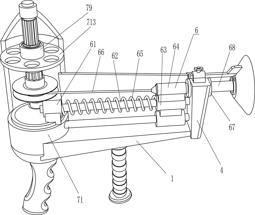
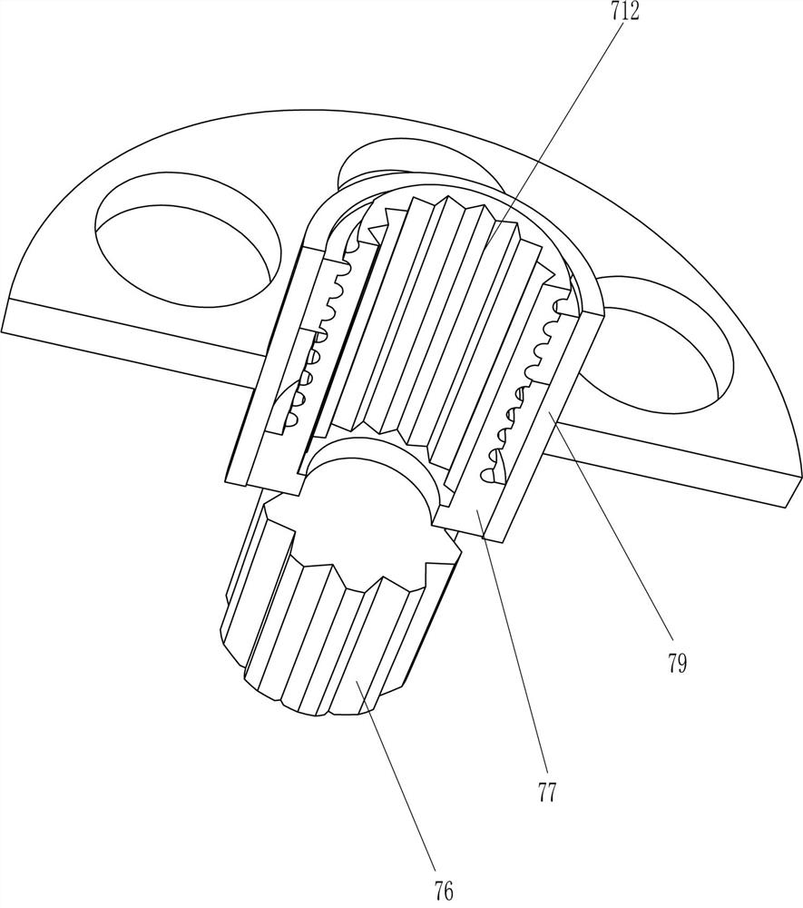
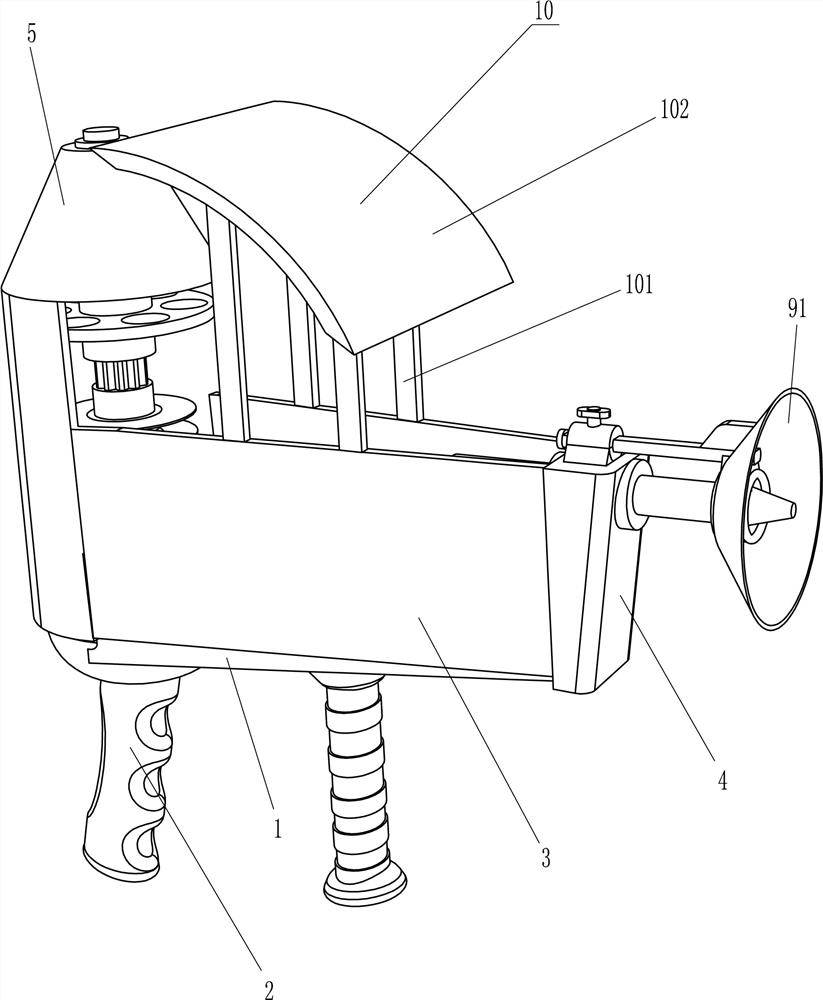
[0053] A plate root percussion device for blanking marble stone slabs, such as figure 1 , 2 As shown, it includes a mounting seat 1, a handle 2, a protective shell 3, a fixing block 4, a conical shell 5, a force accumulating mechanism 6 and a wire take-up mechanism 7. The bottom left side of the mounting seat 1 is provided with a handle 2, and the top of the mounting seat 1 is provided The front and rear sides are symmetrically provided with a protective shell 3, a fixing block 4 is provided on the right side of the top of the mounting seat 1, the fixing block 4 is located on the right side of the protective shell 3, a wire take-up mechanism 7 is provided on the left side of the top of the mounting seat 1, and the left side of the protective shell 3 is provided A conical shell 5 is provided, the upper part of the conical shell 5 is connected with the wire take-up mechanism 7 , and a force storage mechanism 6 is arranged between the wire take-up mechanism 7 and the fixing block...
Embodiment 2
[0056] On the basis of Example 1, as figure 2 , 3 As shown in , 5, the force accumulating mechanism 6 includes a fixed seat 61, a sliding rod 62, a sliding sleeve 63, a fixed sleeve 64, a spring 65, a pulling rope 66, a guide tube 67 and an impact head 68, and the wire take-up mechanism 7 is provided with a fixed The seat 61, a sliding rod 62 is connected between the fixing seat 61 and the fixing block 4, and a sliding rod 62 is also connected between the lower part of the wire take-up mechanism 7 and the fixing block 62, and a sliding sleeve 63 is slidably connected on the sliding rod 62. The sliding sleeve 63 is connected, the top of the sliding sleeve 63 on the upper side is provided with a fixed sleeve 64, a spring 65 is connected between the fixed seat 61 and the sliding sleeve 63, a guide tube 67 is embedded in the upper part of the fixed block 4, and the sliding type inside the fixed block 4 An impact head 68 is connected, and the impact head 68 passes through the fix...
Embodiment 3
[0061] On the basis of the example, as figure 1 and 4 As shown, it also includes a spacer mechanism 8. The spacer mechanism 8 includes a slider 81, a fastening bolt 82, a slide rail 83 and a support ring 84. The top of the fixed block 4 is provided with a slider 81. A slide rail 83 is connected, the top of the slide block 81 is connected with a fastening bolt 82 by means of threads, and the fastening bolt 82 cooperates with the slide rail 83 . .
[0062] When people need to strike the root of the marble stone slab, the position of the slide rail 83 can be adjusted according to the thickness of the stone slab. Thereby, the support ring 84 is driven to move to the left. When the stone slab is thin, the slide rail 83 can move to the right in the slider 81 by tightening the bolt 82, thereby driving the support ring 84 to move to the right, so that the distance of the percussion movement can be controlled. to control the strength of the strike.
[0063] It also includes a prote...
PUM
 Abstract
Description
Claims
Application Information