Novel L-shaped pressure sensor clamp

A sensor and pressure technology, applied in the direction of supporting machines, mechanical equipment, machines/supports, etc., can solve the problems of unsatisfactory sealing effect, reduced work efficiency, accelerated wear and scrap of sealing rings and gaskets, etc., to improve the test The effect of success rate, improving work efficiency and reducing installation time

Inactive Publication Date: 2020-09-29
CHENGDU AIRCRAFT INDUSTRY GROUP
View PDF12 Cites 2 Cited by
  • Summary
  • Abstract
  • Description
  • Claims
  • Application Information

AI Technical Summary

Problems solved by technology

[0004] In practice, due to the limitation of machining accuracy, it is difficult to make the contact surface of the sealing ring and the L-shaped pressure sensor completely fit; due to the torque effect when the handwheel is rotated and tightened, it is easy to make the fixture as a whole relative to the L-shaped pressure sensor. When rotating, there will be a gap on the fitting surface, and the sealing effect is not ideal. Air leakage often occurs during the test, and the test needs to be repeated many times to complete the test.
In addition, when installing, the clamp is inserted directly from the front of the total pressure hole of the L-shaped pressure sensor to the rear. It is not convenient to observe whether the static pressure hole is aligned with the annular groove on the gasket, resulting in time-consuming clamping and reduced work efficiency; sleeve The embedded installation method makes the sealing ring and gasket in the fixture rub against the surface of the L-shaped pressure sensor, which accelerates the wear and tear of the sealing ring and gasket.

Method used


Image

  • Novel L-shaped pressure sensor clamp

Examples


Embodiment 1

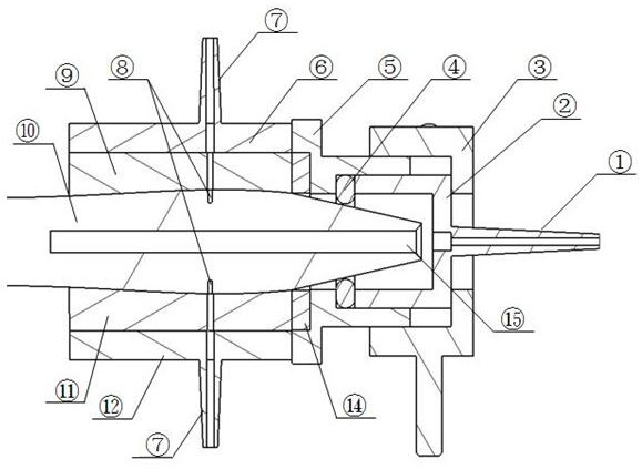
[0019] A novel L-shaped pressure receptor 10 fixture includes an upper casing 6 and a lower casing 12 for fixing the L-shaped pressure receptor 10, and one end of the upper casing 6 and the lower casing 12 is connected with the main body 5 at the same time. Connected, the main body 5 is provided with a sealing ring 4, the main body 5 is provided with a tightening handwheel 3 and a compression sleeve 2, and one end of the main body 5 is provided with a total pressure pipe joint 1. The static pressure part of the special fixture for the L-shaped pressure sensor 10 is clamped and installed up and down, so that the gasket is deformed to ensure a reliable seal; at the same time, the up and down clamping method also facilitates the connection between the air hole on the fixture and the upper part of the L-shaped pressure sensor 10. , The lower static pressure holes 8 are aligned and communicated to reduce the installation time. The clamping is more convenient and fast, and the seali...

Embodiment 2

[0021] A novel L-shaped pressure receptor 10 fixture includes an upper casing 6 and a lower casing 12 for fixing the L-shaped pressure receptor 10, and one end of the upper casing 6 and the lower casing 12 is connected with the main body 5 at the same time. Connected, the main body 5 is provided with a sealing ring 4, the main body 5 is provided with a tightening handwheel 3 and a compression sleeve 2, and one end of the main body 5 is provided with a total pressure pipe joint 1.

[0022] Both the upper shell 6 and the lower shell 12 are provided with a static pressure nozzle 7 , and the other end of the static pressure nozzle 7 communicates with the static pressure hole 8 . An upper gasket 9 is arranged between the upper casing 6 and the L-shaped pressure receptor 10 ; a lower gasket 11 is arranged between the lower casing 12 and the L-shaped pressure receptor 10 .

[0023] The static pressure holes 8 are located on the L-shaped pressure receptor 10 and are aligned with the c...


PUM


Abstract

The invention belongs to the related field of aviation manufacturing and particularly relates to a novel L-shaped pressure sensor clamp. The novel L-shaped pressure sensor clamp is used for connectingground testing equipment with a left L-shaped pressure sensor and a right L-shaped pressure sensor on a machine through testing pipelines when used for an atmospheric data system air-tight test, a ventilation test and a pressure sensor performance test. The novel L-shaped pressure sensor clamp comprises an upper shell and a lower shell which are used for fixing the L-shaped pressure sensors. Oneend of the upper shell and one end of the lower shell are connected with a main body at the same time. A sealing ring is arranged in the main body. A tightening hand wheel and a pressing sleeve are arranged outside the main body. A main pressure pipe joint nozzle is arranged at one end of the main body. A static-pressure part of the L-shaped pressure sensor special clamp adopts an up-down clampingmounting mode, so that a sealing pad is deformed to ensure reliable sealing; meanwhile the up-down mounting mode facilitates aligned communication of a vent hole in the clamp and upper static pressure holes and lower static pressure holes in the L-shaped pressure sensors, and the mounting time is saved; and the clamping operation of the clamp is more convenient and faster, the test success rate is increased, and the working efficiency is improved.

Description

technical field [0001] This application belongs to the field related to aviation manufacturing, and in particular relates to an air-tightness test, ventilation test, and pressure sensor performance test of an air data system. Connected new L-shaped pressure sensor fixture. Background technique [0002] When conducting the air tightness test, ventilation test and pressure sensor performance test of the air data system, the ground test equipment needs to pass through the pipeline through the special fixture and the static pressure hole and total pressure hole of the L-shaped pressure sensor on the machine through the pipeline through the special fixture connected. [0003] The L-shaped pressure sensor is connected to the test pipeline through a special fixture, the total pressure pipe joint is connected to the ground total pressure test pipeline, the total pressure test pipeline, the total pressure pipe joint, and the L-shaped pressure sensor The pressure hole and its intern...

Claims


Application Information

Patent Timeline
Patent Type & Authority Applications(China)
IPC IPC(8): F16M11/04
CPCF16M11/04
Inventor 莫焘苟炜豪王智余漪川
Owner CHENGDU AIRCRAFT INDUSTRY GROUP
Why Eureka
Try Eureka