
Gear grinding fixture adopting end surface drive for small gear shaft

A pinion shaft and end face technology, which is applied in the field of end face drive gear grinding fixtures, can solve the problems of affecting gear grinding accuracy and consistency, poor consistency of gear grinding accuracy, and increasing processing costs, and achieves reliable driving, high positioning accuracy, and operation. easy effect

Inactive Publication Date: 2017-03-22
WUXI WEIFU CHINA ITAL GEAR
View PDF5 Cites 2 Cited by
  • Summary
  • Abstract
  • Description
  • Claims
  • Application Information

AI Technical Summary

Problems solved by technology

For the gear shaft with small outer diameter, after the shaft end is lengthened, the shaft is easy to bend after being stressed, and the rigidity is poor, which affects the accuracy and consistency of gear grinding; in addition, the removal of the lengthened part of the shaft will increase the processing cost. Therefore, the traditional small There are problems such as poor consistency of gear grinding accuracy and high cost in the gear shaft grinding process

Method used


Image

  • Gear grinding fixture adopting end surface drive for small gear shaft

Examples


Embodiment Construction

[0019] The present invention will be further described below in conjunction with specific drawings and embodiments.

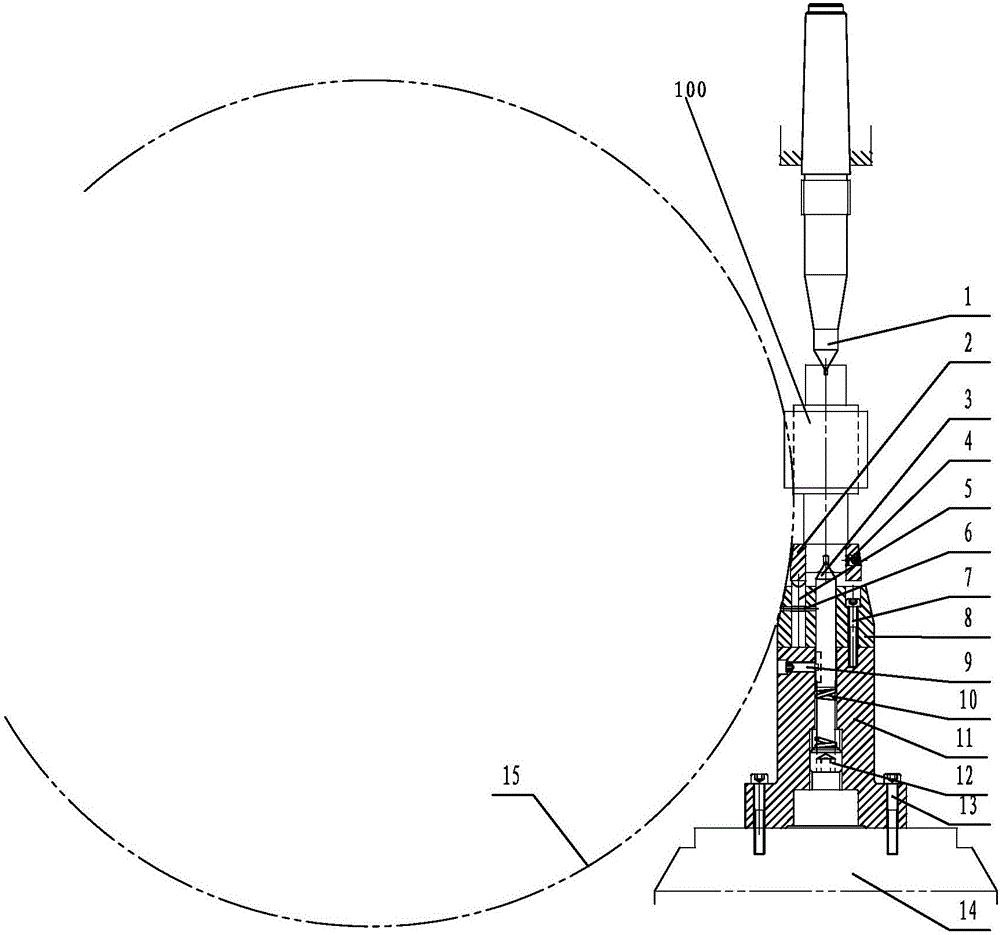
[0020] Such as figure 1 As shown, the end drive pinion shaft grinding jig provided by the present invention includes: upper center 1, clamping sleeve 2, floating center 3, first set screw 4, end pawl 5, pin 6, first set screw 7. Top seat 8, second set screw 9, spring 10, connecting seat 11, adjusting nut 12, second set screw 13, workbench 14;

[0021] The tooth grinding fixture realizes the positioning of the center hole of the gear shaft 100 + the end face driving of the gear shaft 100 through the upper center 1, the clamping sleeve 2, the floating center 3, the first set screw 4, and the end face pawl 5;

[0022] The upper center 1 is installed in the tailstock sleeve of the machine tool, and the axial movement of the upper center 1 is realized by the pressure of the tailstock; the lower end of the upper center 1 withstands the upper center hole of the gear ...


PUM


Abstract

The invention provides a gear grinding fixture adopting end surface drive for a small gear shaft. The gear grinding fixture comprises an upper centre, a clamping sleeve, a floating centre, a first set screw, end surface pawls, pins, a centre seat, a second set screw, a spring, a connection seat and an adjustment nut, wherein the upper centre is installed in a tailstock sleeve of a machine tool, and axial movement of the upper centre is realized by virtue of the pressure of a tailstock; the lower end of the upper centre is abutted against a central hole in the upper end of the gear shaft; the clamping sleeve sleeves the excircle of the lower end of the gear shaft, and is fixed to or released from the gear shaft through the first set screw arranged on the side surface of the clamping sleeve; the centre seat is fixed to the top end of the connection seat; the end surface pawls which are peripherally distributed are arranged on the centre seat, and the pins are embedded in radial holes of the centre seat and the end surface pawls; the end surface pawls are indented in the end surface of the clamping sleeve, which is located above the centre seat; central holes are arranged in the centres of the centre seat and the connection seat, and the floating centre is installed in the central holes; and the upper end of the floating centre is abutted against a central hole in the lower end of the gear shaft due to the elasticity of the spring. The fixture is capable of meeting the requirements of high accuracy and batch machining of gear grinding for the gear shaft.

Description

technical field [0001] The invention relates to a clamp, in particular to a gear grinding clamp driven by an end face. Background technique [0002] Due to the large diameter of the grinding wheel of the gear grinding machine and the influence of factors such as the distance from the center of the grinding wheel to the worktable, the pinion shaft is convenient for gear grinding. The commonly used processing method is: one end of the pinion shaft is lengthened, and then the two tops are positioned for grinding, and finally the Shaft lengthening is removed. For the gear shaft with small outer diameter, after the shaft end is lengthened, the shaft is easy to bend after being stressed, and the rigidity is poor, which affects the accuracy and consistency of gear grinding; in addition, the removal of the lengthened part of the shaft will increase the processing cost. Therefore, the traditional small There are problems such as poor consistency of gear grinding accuracy and high co...

Claims


Application Information

Patent Timeline
Patent Type & Authority Applications(China)
IPC IPC(8): B23F23/06
CPCB23F23/06
Inventor 许智慧林天琪贡庆
Owner WUXI WEIFU CHINA ITAL GEAR
Learn More