Lens unit and method for manufacturing lens unit

A technology of lens unit and manufacturing method, which is applied in the direction of electrical components, optical components, installation, etc., and can solve the problems of high cost, high mechanical strength, and low mechanical strength

Active Publication Date: 2020-09-29
SANKYO SEIKI MFG CO LTD
View PDF7 Cites 1 Cited by
  • Summary
  • Abstract
  • Description
  • Claims
  • Application Information

AI Technical Summary

Problems solved by technology

The former has high mechanical strength but is expensive, while the latter has low mechanical strength but is cheap

Method used


Image

  • Lens unit and method for manufacturing lens unit
  • Lens unit and method for manufacturing lens unit
  • Lens unit and method for manufacturing lens unit

Examples


Embodiment Construction

[0041] Hereinafter, embodiments of the present invention will be described in detail using the drawings.

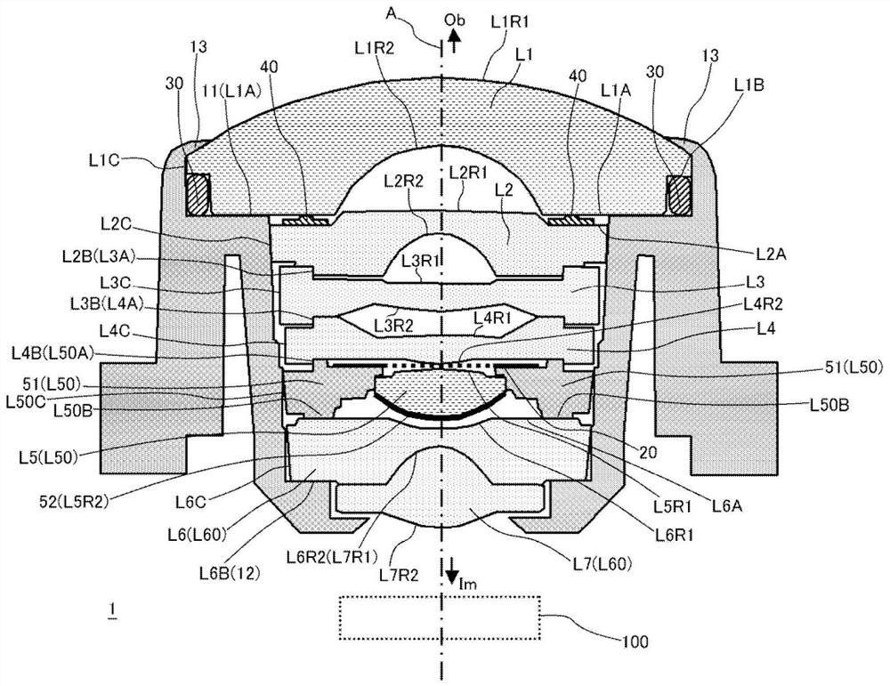
[0042] figure 1 It is a sectional view along the optical axis A of the lens unit 1 according to this embodiment. Here, the object (Ob) side is the upper side in the figure, the image (Im) side is the lower side in the figure, and the imaging element 100 is located at the bottom in the figure. The lenses L1 to L7 are respectively fixed directly or indirectly on the lens barrel 10 . exist figure 1 In the description, it is mainly described that each lens, the diaphragm 20, or the structure for fixing each lens and the lens barrel 10, but actually also has a structure for fixing the positional relationship between the imaging element 100 and the lens barrel 10, but it is omitted. recorded.

[0043] The imaging element 100 is a two-dimensional CMOS image sensor, and pixels are arranged two-dimensionally in a plane perpendicular to the optical axis A. Actually, the imaging...


PUM


Abstract

The invention provides a lens unit and a manufacturing method thereof. The lens unit can adjust the interval between lenses with high precision and is low in cost. A protrusion part L50B which protrudes locally from the periphery of a fifth lens body L50 toward an image side may be provided on an image side of the fifth lens body. On an object side of a cemented lens L60, a cemented lens upper surface L6A abutting against the protrusion part on the outside of a lens surface L6R1 may be provided. The protrusion part may be formed in number at equal intervals in the circumferential direction, and the protrusion parts may be divided into seven protrusion part groups L50B1-L50B7 each including three protrusion parts in accordance with the protrusion amount to the image side. The protrusion part which actually abuts against the cemented lens upper surface L6A may be selected from among the protrusion parts L50B1-L50B7 in accordance with the thickness of a fifth lens L5 as actually measured,so that the interval between the fifth lens and the cemented lens may be of an appropriate value.

Description

technical field [0001] The present invention relates to a lens unit including a plurality of lenses and a barrel for accommodating and fixing them, and a method for manufacturing the same. Background technique [0002] For example, as an optical system used in an imaging device installed in a car, a surveillance camera, etc., a multi-layer optical system arranged in the direction of the optical axis (optical axis of the imaging device) from the object side to the image side (imaging element side) is used. lens unit. The lens unit is designed so that the image of the object formed by visible light is well formed on the camera element. Therefore, it is required to fix the positional relationship between the lenses, the positional relationship between the lenses and the lens barrel, and the lens unit and the imaging element with high precision. [0003] In this case, the lens barrel is made of highly weather-resistant resin material. In addition, as a constituent material of...

Claims


Application Information

Patent Timeline
Patent Type & Authority Applications(China)
IPC IPC(8): G02B7/02
CPCG02B7/021G02B7/023G02B7/025G02B7/022H04N23/55
Inventor 白鸟敏男神崎阳介小宫山忠史
Owner SANKYO SEIKI MFG CO LTD
Why Eureka
Try Eureka