Card edge connection unit

A technology for connection devices and card edge connectors, which is applied to parts, connections, coupling devices, etc. of connection devices, can solve problems such as poor contact, peeling off, insufficient contact pressure, etc., and achieve a stable connection effect

Active Publication Date: 2019-07-02
SMK CO LTD
View PDF1 Cites 0 Cited by
  • Summary
  • Abstract
  • Description
  • Claims
  • Application Information

AI Technical Summary

Problems solved by technology

However, when the tolerance of the thickness of the memory card 2 increases, the biasing force F2 of the leaf spring 5 and the pressing force F1 of the connector 6 will act too strongly, and the contact between the conductive contact surface 6a of the connector 6 and the memory card 2 will be too strong. When the contact group 2a slides, there may be damage such as peeling between the conductive contact surface 6a and the contact group 2a
[0005] Conversely, when the tolerance of the thickness of the memory card 2 is too small, poor contact may occur due to insufficient contact pressure between the conductive contact surface 6a of the connector 6 and the contact group 2a of the memory card 2.

Method used


Image

  • Card edge connection unit
  • Card edge connection unit
  • Card edge connection unit

Examples


Embodiment 1

[0031] Hereinafter, Embodiment 1 of the present invention will be described based on the drawings.

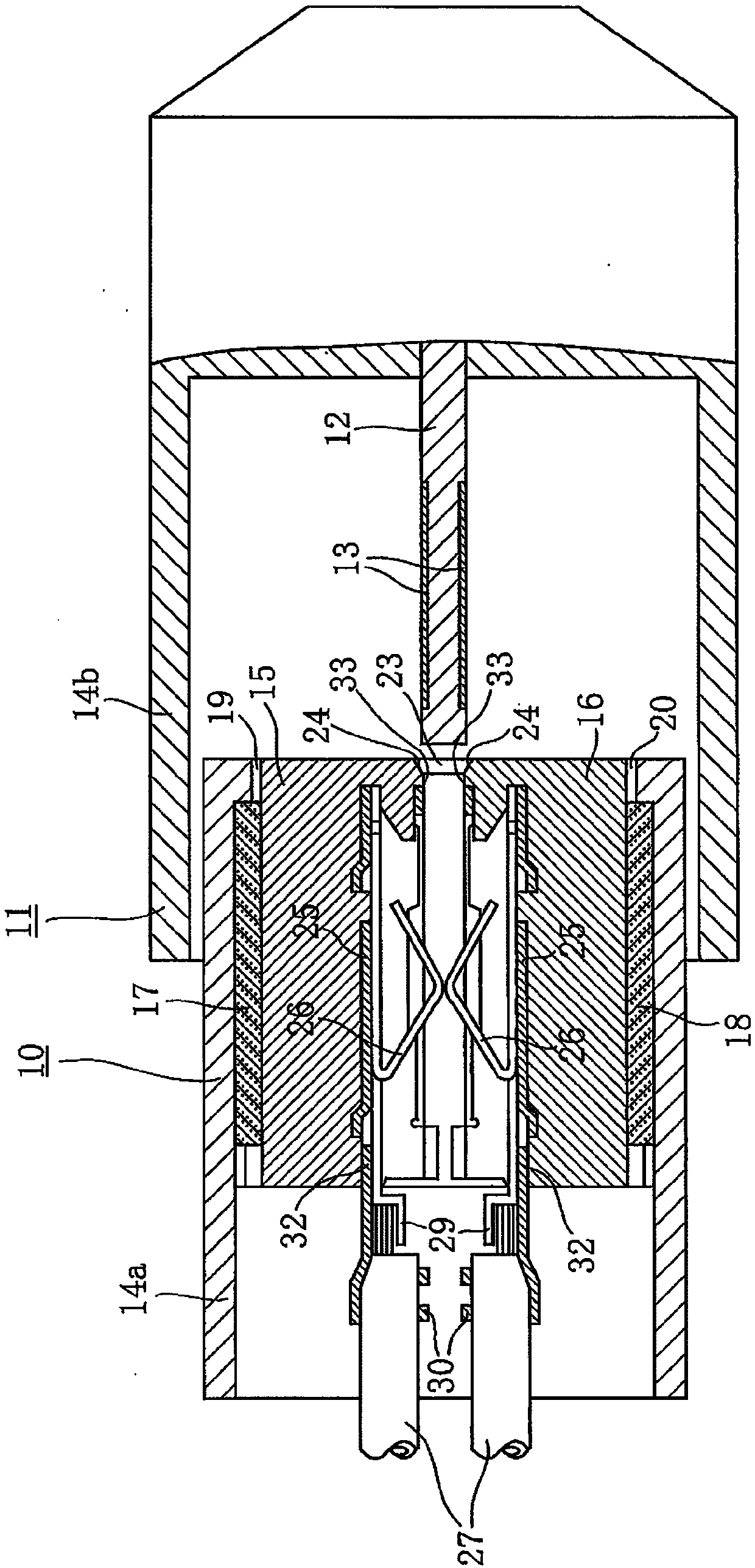
[0032] exist Figure 1 ~ Figure 4 Among them, 10 is a card edge connector, 11 is a card edge assembly, and the card edge connector 10 and the card edge assembly 11 constitute the card edge connection device of the present invention.

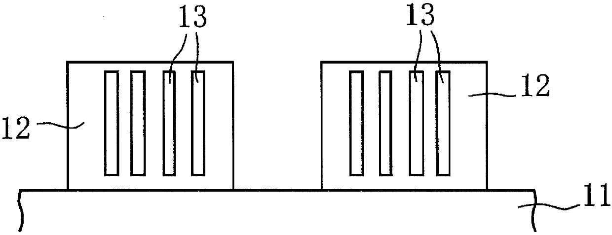
[0033] The card edge assembly 11 protrudes from the inner central part surrounded by the shell 14b with a connecting substrate 12 of a predetermined thickness, and on both sides of the connecting substrate 12 are arranged such as image 3 The electrode set 13 is shown.

[0034] The connecting substrate 12 is set to be, for example, 1.6 mm thick, and a tolerance of ±10% is allowed. Even if the connection board 12 has such a tolerance, it is desired to connect it to the card edge connector 10 stably and reliably, and the present invention aims to solve this problem.

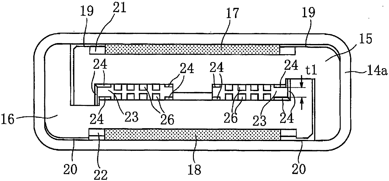
[0035] The card edge connector 10 for this purpose is constructed as follows. ...

Embodiment 2

[0053] In the above-mentioned embodiment, the case where the electrode groups 13 are provided on both sides of the connection substrate 12 is described, so an example is shown in which the card edge connector 10 has a pair of elastic contacts 26 in contact with the electrode groups 13 on both sides.

[0054] However, the present invention is not limited thereto, and when the connection substrate 12 has the electrode group 13 on one side, the card edge connector 10 may have the elastic contact 26 in contact with the electrode group 13 on the one side. For example, in the case where the elastic contacts 26 are provided only on the lower inner case 16 side, it may also be configured such that the lower elastic body 18 is sandwiched between the lower inner case 16 and the outer case 14a, and the upper inner case The elastic contacts 26 and the upper elastic body 17 are not provided on the side of the body 15, and the connecting substrate 12 does not move forward or backward even wh...


PUM


Abstract

Even when a connection board has a large thickness tolerance, a stable connection is achieved by absorbing the tolerance so as to stabilize a contact pressure between the connection board and contacts. In a unit in which electrode groups (13) of a connection board (12) are in pressure contact with elastic contacts (26) formed integrally with an inner housing (15) to connect thereto, the inner housing (15) is provided inside an outer case (14a) of a card edge connector (10) through an elastic member (17) to be freely movable forward and backward in a thickness direction of the connection board(12). The positions of the elastic contacts (26) are adjusted by forward or backward moving the inner housing (15) in accordance with the thickness of the connection board (12) inserted into board insertion slots (23), so a pressure contact force with the elastic contacts (26) is substantially equalized, irrespective of the size of the thickness of the connection board (12).

Description

technical field [0001] The invention relates to a card edge connection device, which inserts the connection substrate of the card edge assembly into the card edge connector for connection, and the card edge connection device can absorb the tolerance of the thickness of the connection substrate to realize stable connection. Background technique [0002] Figure 6 It is a conventional device for electrically connecting a memory card 2 to a connector 6 of an electronic device 1 (Patent Document 1). [0003] In this figure, when the memory card 2 is inserted into the insertion opening 1 a of the device main body 1 , the memory card 2 is guided by the slope 3 a of the protrusion 3 and attached to a position where it abuts against the stopper. In this installed position, the memory card 2 is positioned at a predetermined height by the protrusion 3 . Moreover, by the biasing force F2 of the plate spring 5, the connector 6 made of conductive rubber is more or less compressed throug...

Claims


Application Information

Patent Timeline
Patent Type & Authority Applications(China)
IPC IPC(8): H01R12/72H01R13/11H01R13/502H01R13/627H01R13/631H01R27/00
CPCH01R13/631H01R13/11H01R13/627H01R13/502H01R27/00H01R12/721H01R12/87H01R13/6315H01R4/18H01R13/2407H01R13/629H01R12/7005H01R12/89
Inventor 铃木悟吉田光宏上原省吾奥村晋也
Owner SMK CO LTD
Why Eureka
Try Eureka