Self-locking circuit for mobile lighting equipment and mobile lighting equipment

A technology of self-locking circuit and mobile lighting, which is applied in the direction of lighting and heating equipment, components of lighting devices, and damage prevention measures of lighting devices. The unlocking method is complicated and cumbersome, etc.

Active Publication Date: 2020-10-02
东莞市傲雷移动照明设备有限公司
View PDF7 Cites 0 Cited by
  • Summary
  • Abstract
  • Description
  • Claims
  • Application Information

AI Technical Summary

Problems solved by technology

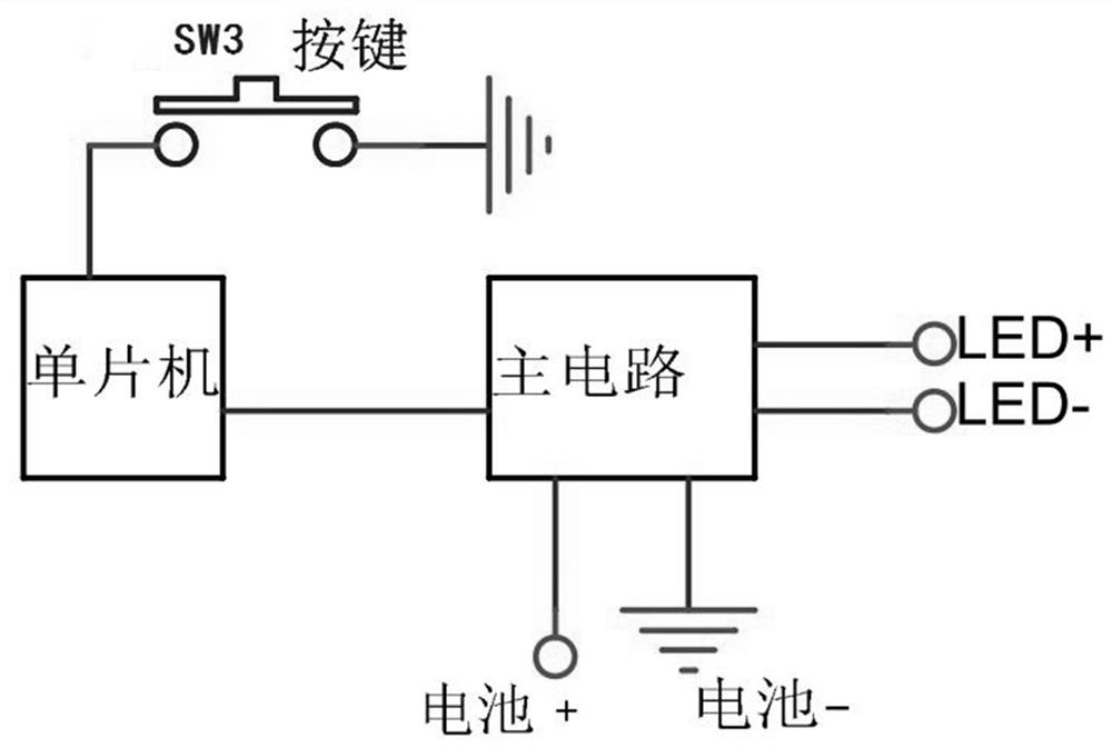
However, this key locking method makes the circuit design of the key locking / unlocking complex, and the unlocking steps are cumbersome. When using the product, the user must read the manual in detail and learn the key locking / unlocking method, and at the same time remember its usage method
Unlock by long pressing the button, even when the mobile lighting device is squeezed by a hard object for a long time, it can also be unlocked, which is prone to accidental unlocking
[0004] Therefore, the current mobile lighting equipment has the problems of complex and cumbersome locking and unlocking methods, and a high rate of false unlocking.

Method used


Image

  • Self-locking circuit for mobile lighting equipment and mobile lighting equipment
  • Self-locking circuit for mobile lighting equipment and mobile lighting equipment
  • Self-locking circuit for mobile lighting equipment and mobile lighting equipment

Examples


Embodiment Construction

[0028] Embodiments of the present invention are described in detail below, examples of which are shown in the drawings, wherein the same or similar reference numerals designate the same or similar elements or elements having the same or similar functions throughout. The embodiments described below by referring to the figures are exemplary and are intended to explain the present invention and should not be construed as limiting the present invention.

[0029] In describing the present invention, it should be understood that the terms "length", "width", "upper", "lower", "front", "rear", "left", "right", "vertical", The orientation or positional relationship indicated by "horizontal", "top", "bottom", "inner", "outer", etc. are based on the orientation or positional relationship shown in the drawings, and are only for the convenience of describing the present invention and simplifying the description, rather than Nothing indicating or implying that a referenced device or element...


PUM


Abstract

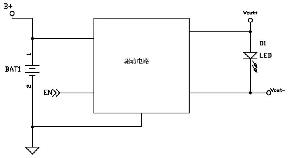
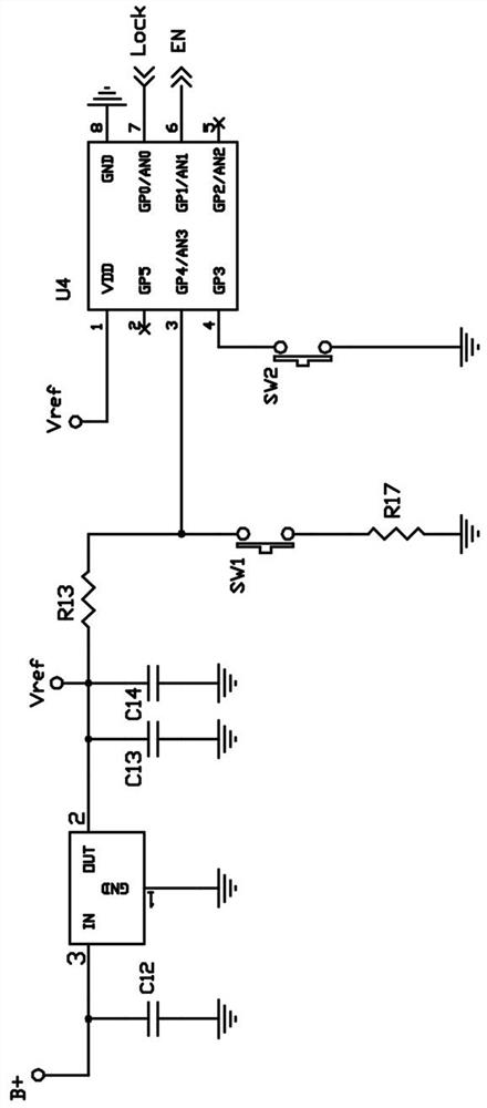
The invention provides a self-locking circuit for mobile lighting equipment. The self-locking circuit comprises a switching circuit and a driving circuit, the driving circuit is connected with a micro-control unit, the micro-control unit is connected with the switching circuit, the micro-control unit is connected with a magnetic induction self-locking circuit, and the micro-control unit is used for detecting a self-locking signal sent by the magnetic induction self-locking circuit and locking the switching circuit. The magnetic induction self-locking circuit sends out a self-locking signal according to the magnetic field characteristic of the external environment; when the lighting device is placed in a specific locking environment, the magnetic induction self-locking circuit senses the specific magnetic field change of the external environment and transmits self-locking information to the micro-control unit; the micro-control unit locks the switch circuit; the locked switching circuitcannot trigger the driving circuit to enable the mobile lighting device to emit light, locking of the mobile lighting device is achieved, the self-locking circuit enables the device to be locked onlyby being placed in a specific environment, and a user does not need to learn complex and tedious unlocking / locking steps.

Description

technical field [0001] The invention belongs to the technical field of mobile lighting equipment, and relates to a self-locking circuit for mobile lighting equipment and the mobile lighting equipment. Background technique [0002] Mobile lighting devices (such as flashlights) are widely used in daily life and processing and production because of their portability and easy operation. However, due to the portability of general mobile lighting equipment, users will put the equipment in their pockets or store it in other spaces with sundries. If the equipment is lit, if the user does not find out in time, it will seriously consume the power of the equipment, especially for mobile lighting equipment with high power, if it is turned on for a long time, it may cause a fire due to excessive temperature. [0003] In order to solve the problem of false touches of mobile lighting equipment, the current common method is to lock the keys through software, such as figure 1 As shown, the...

Claims


Application Information

Patent Timeline
IPC IPC(8): F21L4/00F21V15/00F21V23/00F21V23/04H05B45/34H03K17/90
CPCH05B45/34H03K17/90F21L4/005F21V23/003F21V23/0442F21V15/005Y02B20/40
Inventor 蒋乐
Owner 东莞市傲雷移动照明设备有限公司
Why Eureka
Try Eureka