Mounting structure of water pressure testing equipment for building construction and testing equipment
A hydraulic testing and building construction technology, applied in the direction of applying stable tension/pressure to test the strength of materials, measuring devices, testing of mechanical components, etc., can solve the problem that the water inlet of the workpiece cannot be aligned with the water outlet, and the universality of the test equipment is limited limit and other issues
- Summary
- Abstract
- Description
- Claims
- Application Information
AI Technical Summary
Problems solved by technology
Method used
Image
Examples
Embodiment 1
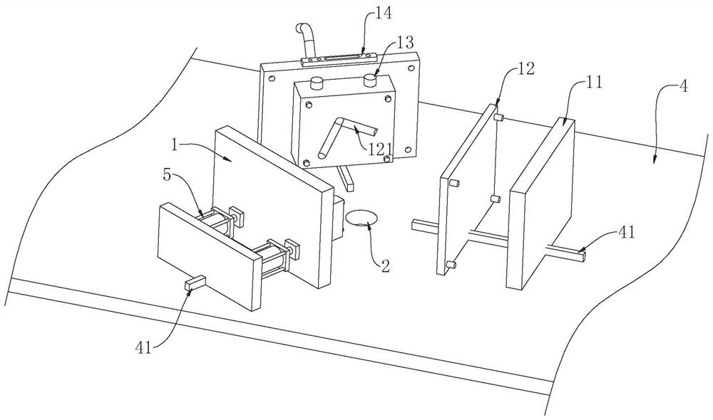
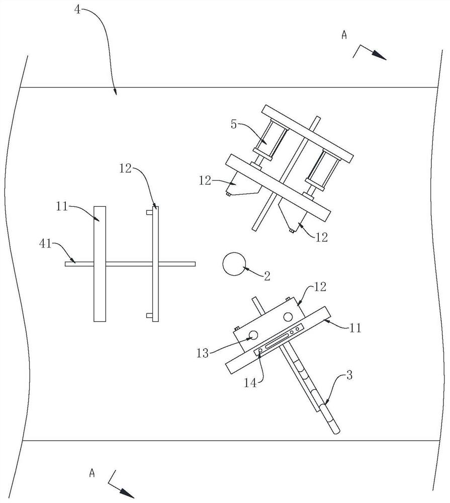
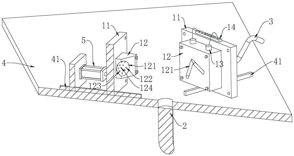
[0044] This embodiment provides an installation structure for water pressure testing equipment for building construction, including: a plurality of fixed units 1, the fixed unit 1 includes a base plate 11 and at least one functional board 12 detachably arranged on the base plate 11, on the functional board 12 A supporting surface is provided, and the functional board 12 has a first position and a second position. When the functional board 12 is located at the first position, the supporting surfaces on the plurality of fixing units 1 form a fixed space for fixing workpieces. At least one functional board 12 is located at the first position. In the second position, the workpiece is in a relaxed state. The base plate 11 provides a basic fixed foundation for the workpiece, and the functional board 12 provides a support surface suitable for the shape of the current workpiece according to the type of the workpiece, thereby forming a corresponding fixed space. When different workpiec...
Embodiment 2
[0054] This embodiment provides a kind of water pressure testing equipment for building construction, including a frame 4, the installation structure of the water pressure testing equipment for building construction in Embodiment 1, the fixed unit 1 is movably connected on the frame 4, and the fixed unit 1 has at least Two, the fixed unit 1 surrounds the fixed area; the driving mechanism 5 is arranged on the frame 4 and acts on the fixed unit 1 to control the movement of the function board 12 between the first position and the second position. The frame 4 has a mounting portion for mounting the fixing unit 1. In the present embodiment, the mounting portion guides the slide rail 41, and the drive mechanism 5 pushes the fixing unit 1 to slide along the guide slide rail 41. When driving the function plate 12 to move to the first position, the driving mechanism 5 promotes the fixing unit 1 to move towards the center of the fixing area. A plurality of fixing units 1 move to the cen...
Embodiment approach
[0055] The specific form of the drive mechanism 5 is not specifically limited, in this embodiment, such as figure 1 , image 3 As shown, the driving mechanism is composed of an air cylinder or a hydraulic cylinder. As an alternative embodiment, the driving mechanism is a combination of an air cylinder or a hydraulic cylinder and a linkage. As another alternative embodiment, the driving mechanism is a rack and pinion or a worm gear transmission mechanism.
[0056] The shape of the guide rail 41 is not specifically limited, in this embodiment, as figure 2 , Figure 4 The shown linear guide rail is only used to illustrate that each fixed unit 1 has a movement tendency to move closer to the fixed area of the center. As an alternative embodiment, the guide rail 41 is curved, or is a motion track of other shapes adapted to drive the fixing unit 1 to clamp the workpiece and loosen the motion of the workpiece.
[0057] The building construction water pressure testing equipment...
PUM
 Abstract
Description
Claims
Application Information
 - R&D
- Intellectual Property
- Life Sciences
- Materials
- Tech Scout
- Unparalleled Data Quality
- Higher Quality Content
- 60% Fewer Hallucinations
Browse by: Latest US Patents, China's latest patents, Technical Efficacy Thesaurus, Application Domain, Technology Topic, Popular Technical Reports.
© 2025 PatSnap. All rights reserved.Legal|Privacy policy|Modern Slavery Act Transparency Statement|Sitemap|About US| Contact US: help@patsnap.com


