
Building force balance monitoring system based on passive sensor network

A passive sensor and force balance technology, applied in the information field, can solve the problems of consuming a lot of manpower and material resources, wasting funds, and the inability of the sensor network to work, so as to improve quality and safety and reduce the waste of battery energy.

Active Publication Date: 2022-03-22
DALIAN UNIV
View PDF3 Cites 0 Cited by
  • Summary
  • Abstract
  • Description
  • Claims
  • Application Information

AI Technical Summary

Problems solved by technology

However, traditional wireless sensors are powered by batteries. Once the sensor battery is out of power, the sensor network cannot work.
Moreover, a lot of manpower and material resources will be consumed in the later battery replacement process, a large number of battery replacements will also cause environmental waste, and long-term replacements will also cause a lot of money waste

Method used


Image

  • Building force balance monitoring system based on passive sensor network
  • Building force balance monitoring system based on passive sensor network
  • Building force balance monitoring system based on passive sensor network

Examples


Embodiment 1

[0018] Embodiment 1: a kind of building force balance monitoring system of passive sensor network, comprises the several nodes that are arranged in the same building surface of building or are arranged in the supporting surface of bridge, and node is mainly collected by pressure sensor module, radio frequency signal module and network module, the sensing surface of the pressure sensing module collects the pressure information of the building and transmits it to the pressure sensor module, the pressure sensor module receives the electric energy provided by the radio frequency signal acquisition module, converts the pressure information into data, and uploads it to the network through the network module , the capacitance of the radio frequency signal acquisition module is less than the set threshold, and the pressure sensor module enters the sleep state. At this time, the radio frequency signal is collected by the radio frequency signal acquisition module and converted into electr...

Embodiment 2

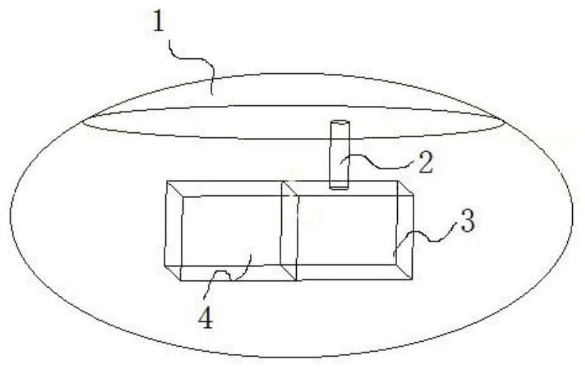
[0092] Embodiment 2: as figure 1 The structure diagram of the smart pebble is shown, which is composed of a pressure sensing module, a data transmission rod, a radio frequency signal acquisition module, and a pressure sensor module. The pressure sensor module senses the pressure information and transmits it to the pressure sensor module through the data transmission rod. The pressure sensor module uses the electric energy provided by the radio frequency signal acquisition module to convert and analyze the pressure information into data, and uploads it to the routing network through the built-in antenna for processing. When the capacitance of the radio frequency signal acquisition module is less than a certain threshold, it will enter the sleep state to collect radio frequency signals and convert them into electric energy. When the electric energy stock reaches a high threshold, it will switch from the sleep state to the active state for data collection.

[0093] The following ...


PUM


Abstract

The building force balance monitoring system of passive sensor network belongs to the field of information technology. In order to solve the problem that the pressure sensor is easier to charge in the building force monitoring, it includes laying it in the same building surface of the building or laying it on the support of the bridge Several nodes in the plane, the nodes are mainly composed of a pressure sensor module, a radio frequency signal acquisition module, and a network module. The sensing surface of the pressure sensing module collects the pressure information of the building and transmits it to the pressure sensor module. Electric energy, and the pressure information is converted into data, which can be uploaded to the network through the network module, and the effect is that the pressure sensor is easier to charge.

Description

technical field [0001] The invention belongs to the field of information technology and relates to a real-time monitoring system for force balance of buildings based on a passive sensor network. Background technique [0002] In terms of building safety detection, the X-ray method, eddy current method, optical diagnostic method, etc., which are commonly used in China at first, judge the safety status of the overall building through the detection of local buildings, but this detection method has great shortcomings. . With the development of information technology, some people use optical fiber communication technology to detect remote buildings. However, this method has limitations in both area of ​​use and performance. After that, people began to use wireless sensors to install and lay out the bridge structure to detect its health. However, sensors are deployed throughout the bridge structure. If the bridge structure is relatively small, it is okay, but if the bridge struc...

Claims


Application Information

Patent Timeline
Patent Type & Authority Patents(China)
IPC IPC(8): H04W4/38H04W4/33G08B21/18G08B5/36G01L5/00G01L19/12
CPCH04W4/38H04W4/33G08B21/182G08B5/36G01L5/00G01L19/12
Inventor 汪祖民郑祖朋季长清秦静
Owner DALIAN UNIV
Learn More