Plugging device and plugging method for optical fiber component

A technology for plugging and unplugging devices and optical fiber components, which is applied in the field of optical module coupling, and can solve problems such as plugging and unplugging lateral deviation of connectors, and achieve the effect of convenient alignment

Active Publication Date: 2022-03-11
GUANGXUN SCI & TECH WUHAN
View PDF5 Cites 0 Cited by
  • Summary
  • Abstract
  • Description
  • Claims
  • Application Information

AI Technical Summary

Problems solved by technology

[0004] In view of this, the embodiment of the present application expects to provide a plugging device and a plugging method for an optical fiber component, so as to solve the problem that the connector of the fiber component is deflected during the process of plugging and unplugging

Method used


Image

  • Plugging device and plugging method for optical fiber component
  • Plugging device and plugging method for optical fiber component
  • Plugging device and plugging method for optical fiber component

Examples


Embodiment Construction

[0056] It should be noted that, in the case of no conflict, the embodiments in the application and the technical features in the embodiments can be combined with each other. Undue Limitation of This Application.

[0057] The terms in the description of the application are only for the convenience of describing the application and simplifying the description, rather than indicating or implying that the device or element referred to must have a specific orientation, be constructed and operated in a specific orientation, and therefore cannot be construed as limiting the application .

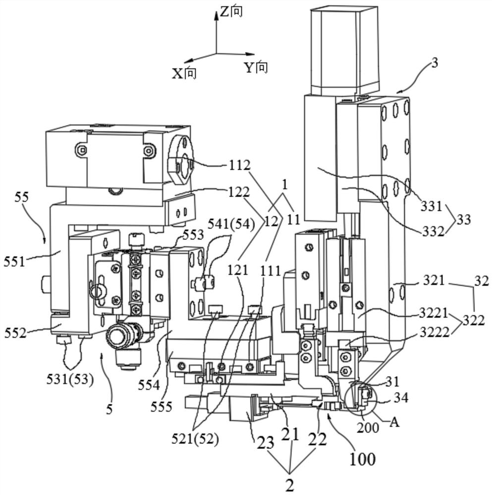
[0058] The X-direction, Y-direction and Z-direction described in the embodiment of this application are all based on the attached figure 1 The directions shown are for reference, wherein the Y direction is the insertion and extraction direction of the optical fiber assembly 100 , and the X and Z directions are both perpendicular to the insertion and extraction direction of the optical fiber assemb...


PUM


Abstract

The present application provides a device for inserting and extracting an optical fiber assembly and a method for inserting and extracting the optical fiber assembly, which are used for inserting or extracting the optical fiber assembly into or from the lens assembly. The plugging device includes a push-pull part, a fixing part, a material picking part and a positioning part. The first fixing part of the fixing part can move relative to the fixing body along a plane perpendicular to the plugging-out direction, and the first fixing part is used for fixing the connector at one end of the optical fiber assembly. The positioning jaws of the positioning part are connected to the positioning driving part, and the positioning driving part controls the positioning jaws to clamp the first fixing part so that the connecting head is aligned with the lens assembly, and the positioning jaws loosen the first fixing part, and the configuration is only for the first fixing part. The fixture provides support in the direction of gravity. In the plug-in device provided by this application, during the process of inserting the optical fiber assembly into the lens assembly, the positioning jaws only provide support in the direction of gravity for the connector, so that no lateral force is generated on the connector, effectively reducing the impact on the optical fiber. Risk of component sideways deflection during insertion into the lens assembly.

Description

technical field [0001] The present application relates to the technical field of optical module coupling, in particular to a plugging device and a plugging method for optical fiber components. Background technique [0002] In the production and manufacture of optical modules, such as the coupling process of 100G COB optical fiber, it is usually necessary to package the lens assembly and the circuit board together through dispensing and curing, and a light source is required to provide energy for it during the dispensing and curing process. Usually, the light energy provided by the light source is transmitted to the lens assembly through the optical fiber, and the required light energy is formed after being processed by the lens assembly. Optical fiber components are usually composed of optical fibers and connectors connected to the ends of the optical fibers. During the coupling process of optical fibers and lenses, the size of the positioning pinholes and positioning pins i...

Claims


Application Information

Patent Timeline
Patent Type & Authority Patents(China)
IPC IPC(8): G02B6/38
CPCG02B6/3898
Inventor 吴卫杨波谭书伟张园
Owner GUANGXUN SCI & TECH WUHAN
Why Eureka
Try Eureka