Rail clamping device

A technology of rail clamps and rails, which is applied in the direction of formwork/formwork/work frame, erection/assembly of bridges, connectors of formwork/formwork/work frame, etc. Control difficulty and other issues, to achieve the effect of short start-up work stroke, reduce control difficulty, and avoid equipment overturning

Pending Publication Date: 2022-07-08
CCCC WUHAN HARBOR ENG DESIGN & RES
View PDF4 Cites 0 Cited by
  • Summary
  • Abstract
  • Description
  • Claims
  • Application Information

AI Technical Summary

Problems solved by technology

However, the above structure can only be fixed during one-way movement, which is inconvenient to use
In CN 106567550 A, a full-automatic two-way hydraulic rail clamp is described, in which a two-way wedge is used for fixing, and the wedge is driven by the opening and closing action of the inclined wedge sliding cylinder. This scheme has the following Defects, one is that the fixing action of the rail clamp is driven by the wedge sliding cylinder, that is, if even one side of the wedge sliding cylinder fails, it may lead to a major safety accident
The second is that the structure is relatively complex, especially during the fixing process, the shell is subjected to a large force, and the overly complex structure leads to an increase in volume
The fourth is to increase the control parts of the oblique wedge sliding cylinder, that is, each push needs to control the action of two oblique wedge sliding cylinders, which increases the difficulty of control

Method used


Image

  • Rail clamping device
  • Rail clamping device
  • Rail clamping device

Examples


Embodiment 1

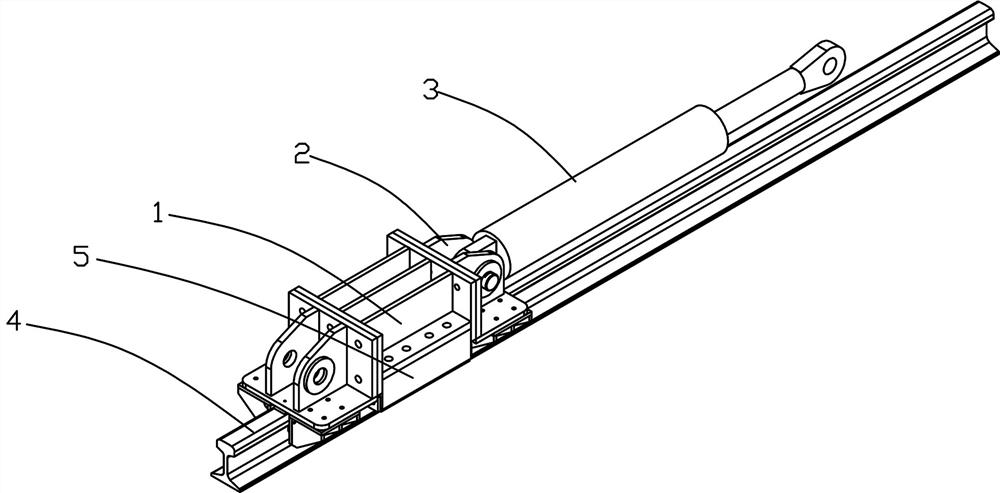
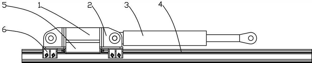
[0036] like Figures 1~4 Among them, a rail clamp includes a clamping seat 1, a connecting seat 2 and a reverse pulley seat 6. There are baffle plates 5 on both sides of the clamping seat 1, and an "X"-shaped space is formed between the baffle plates 5 on both sides. A wedge 108 is provided in the cavity formed by the baffles 5 on both sides, and the wedge 108 is provided with an inclined surface. The inclined surface of the wedge 108 is in contact with the inclined surface of the inner wall of the cavity formed by the baffle One side is the working surface 123, and the working surface 123 is used to contact the side surface of the track 4;

[0037] The connecting seat 2 is fixedly connected with the clamping seat 1, the connecting seat 2 is located at at least one end of the clamping seat 1, and the connecting seat 2 is used for connecting with the driving mechanism 3;

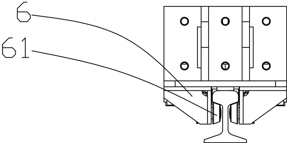
[0038] like figure 2 , 3 In the middle, the reverse hook wheel seat 6 is fixedly connected with the co...

Embodiment 2

[0042] On the basis of Example 1, the preferred scheme is as follows Figure 5 In the middle, a friction block 107 is provided at the position where the baffle 5 is in contact with the wedge block 108. The friction block 107 is made of wear-resistant material, such as wear-resistant rubber or wear-resistant steel block, such as high-chromium steel. The friction block 107 is connected to the The baffle 5 is fixedly connected. With this configuration, it is possible to reduce the service life of the parts that are difficult to replace. And the wedge 108 is correspondingly easy to replace.

Embodiment 3

[0044] On the basis of embodiment 1 or 2, the preferred scheme is as follows Figure 5 The two ends of the cavity formed by the baffle 5 are also provided with adjusting nuts 105 , and a spring 106 is provided between the adjusting nut 105 and the wedge 108 , and the spring 106 is used to pre-compress the wedge 108 . With this structure, the preloading force can be adjusted to shorten the starting working stroke as much as possible, and the starting working stroke refers to the stroke from starting to complete locking. Moreover, the adjustment of the pre-tightening force of the adjusting nut 105 can also control the rail clamp to achieve one-way locking, which is very effective in the working condition of jacking. tight, as Figure 5 The adjustment nut 105 on the left side of the Figure 5The right side adjusting nut 105 in the middle, when the drive mechanism 3, usually the piston rod of the hydraulic cylinder, is retracted, because the wedge 108 close to the hydraulic cyli...


PUM


Abstract

The rail clamping device comprises a clamping base, a connecting base and a reverse hooking wheel base, baffles are arranged on the two sides of the clamping base, an X-shaped cavity is formed between the baffles on the two sides, a wedge block is arranged in the cavity formed by the baffles on the two sides, the wedge block is provided with an inclined face, the inclined face of the wedge block makes contact with the inclined face of the inner wall of the cavity formed by the baffles, and the other face, opposite to the inclined face of the wedge block, of the wedge block is a working face. The working surface is contacted with the side surface of the track; the connecting seat is fixedly connected with the clamping seat, the connecting seat is located at least one end of the clamping seat, and the connecting seat is used for being connected with a driving mechanism; the reverse hooking wheel base is fixedly connected with the connecting base and located below the connecting base, and reverse hooking wheels are arranged on the two sides of the reverse hooking wheel base and used for being hooked to the lateral lower portion of a track. And through the combination of the clamping seat and the reverse hooking wheel seat, the equipment is prevented from overturning. The structure of the four wedge blocks is arranged, so that bidirectional fixation can be realized, and the device is particularly suitable for large-scale pushing and jacking equipment, such as bridge pushing construction, construction of large-scale creeping formworks and stair climbing machines, and other working conditions.

Description

technical field [0001] The present invention relates to a locking and fixing device, in particular to a rail clamp. Background technique [0002] In the process of engineering construction, some equipment or components need to move along the track, and during the movement, to fix the equipment or components, the rail clamp is usually used as the fixed part. In the rail clamp, the use of wedges is more common. structure. For example the structures in CN 112897336 A, CN 111674861 A and CN 213707535 U. However, the above structure can only be fixed during one-way movement, which is relatively inconvenient to use. CN 106567550 A describes a fully automatic two-way hydraulic rail clamp, wherein two-way wedges are used to achieve fixation, and the wedge is driven by the opening and closing action of the wedge sliding oil cylinder. The solution has the following Defects, one is that the fixed action of the rail clamp is driven by the wedge sliding cylinder, that is, if the wedge...

Claims


Application Information

Patent Timeline
Patent Type & Authority Applications(China)
IPC IPC(8): E01D21/00E04G11/28E04G17/00E04G21/00
CPCE01D21/00E04G11/28E04G17/00E04G21/00
Inventor 张超胥奇田涛王磊余汉锦刘斌李天成孙灿余龙飞王臻
Owner CCCC WUHAN HARBOR ENG DESIGN & RES
Why Eureka
Try Eureka