Pre-twisted fitting for aerial optical cable

An overhead optical cable, pre-twisted technology, used in optical fiber/cable installation, optics, light guide, etc., can solve the problems of inability to stretch force, buffer unloading force and energy absorption, twisted wire pulling deformation, poor tensile resistance, etc. Practical and convenient, the effect of eliminating stress concentration and avoiding fracture

Inactive Publication Date: 2020-10-02
JIANGSU HUAMAI NEW MATERIAL CO LTD
View PDF13 Cites 3 Cited by
  • Summary
  • Abstract
  • Description
  • Claims
  • Application Information

AI Technical Summary

Problems solved by technology

[0004] The purpose of the present invention is to solve the disadvantages in the prior art that the stretch resistance performance is poor, the tensile force cannot be buffered and unloaded and energy absorbed, and there is deformation of twisted wire, loss of grip force, and eventually damage to the cable. Pre-twisted fittings for overhead optical cables

Method used


Image

  • Pre-twisted fitting for aerial optical cable
  • Pre-twisted fitting for aerial optical cable
  • Pre-twisted fitting for aerial optical cable

Examples


Embodiment 1

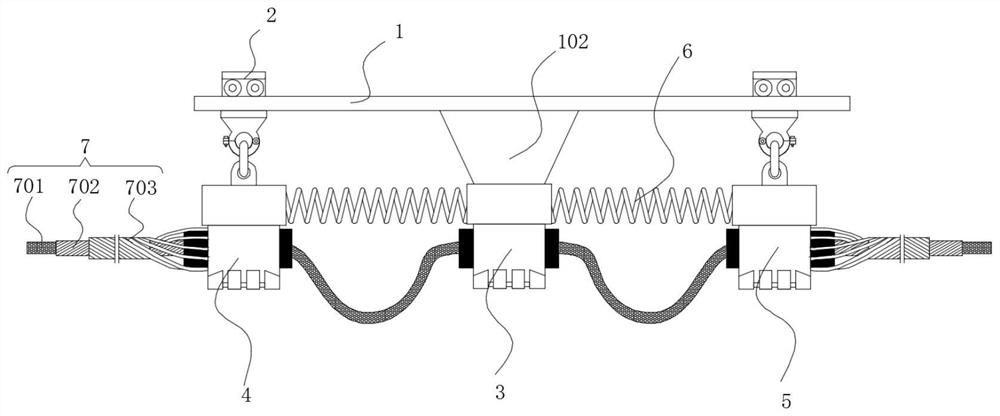
[0029] refer to Figure 1-3 with Figure 8 , including a mounting bracket 1, a movable component 2, a support component 3, a left fixed component 4, a right fixed component 5 and an optical cable component 7, the support component 3 is fixedly arranged in the middle of the mounting bracket 1, and the movable component 2 is provided with two groups and installed movably On the mounting brackets 1 on both sides of the support member 3, the left fixed assembly 4 and the right fixed assembly 5 are respectively connected to the movable assemblies 2 on both sides, and the optical cable assembly 7 is fixed through the left fixed assembly 4, the support member 3 and the right fixed assembly 5 Connection, the support member 3 is fixedly connected with the left fixing component 4 and the right fixing component 5 through rigid springs 6 respectively.

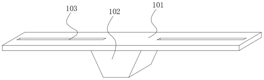
[0030] The mounting bracket 1 includes a mounting plate 101 and a supporting boss 102. The supporting boss 102 is integrally formed in t...

Embodiment 2

[0036] refer to Figure 4-8 The difference between this embodiment and the embodiment is that the structure of the movable assembly 2 is different. In this embodiment, the mounting bracket 1 includes a mounting plate 101 and a supporting boss 102, and the supporting boss 102 is integrally formed in the middle of the mounting plate 101. The two ends of mounting plate 101 are provided with rotation slotted hole 104, and two groups of movable assemblies 2 are installed in rotation slotted hole 104 places and are movably connected with left fixed assembly 4, right fixed assembly 5 by elastic telescoping rod 8.

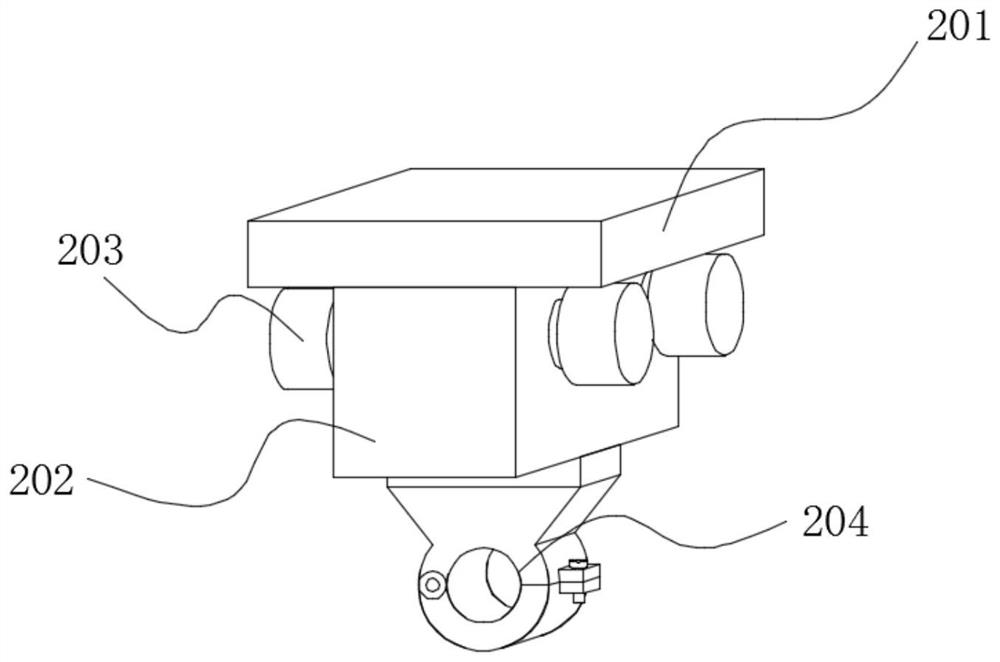
[0037]The movable assembly 2 comprises a limiting disc 207, a rotating shaft 205 and a support ring 206, the rotating shaft 205 is integrally formed on the lower side of the limiting disc 207, the lower end of the rotating shaft 205 is integrally formed with a supporting ring 206, and the rotating shaft 205 The support ring 206 passing through the sliding groove 103 and it...


PUM


Abstract

The invention discloses a pre-twisted fitting for an aerial optical cable, relating to the field of electric power fittings. The optical cable comprises mounting brackets, movable assemblies, a supporting piece, a left fixing assembly, a right fixing assembly and an optical cable assembly. The supporting piece is fixedly arranged in the middles of the mounting brackets, and the two movable assemblies are movably installed on the mounting bracket on the two sides of the supporting piece. The left fixing assembly and the right fixing assembly are connected with the movable assemblies on the twosides respectively, the optical cable assembly penetrates through the left fixing assembly, the supporting piece and the right fixing assembly to be fixedly connected, and the supporting piece is fixedly connected with the left fixing assembly and the right fixing assembly through rigid springs respectively. Through the spiral line structure of the inner and outer double-layer twisted wires, the grip to the optical cable is improved, and the reliability of optical cable connection is ensured; and meanwhile, the wind resistance and the pulling resistance of the connected cable are improved while the rigid strength of connection is ensured, the optical cable is prevented from being broken due to too strong stress, and the service life of the optical cable is prolonged.

Description

technical field [0001] The invention relates to the field of electric fittings, in particular to a pre-twisted fitting for overhead optical cables. Background technique [0002] Power fittings are metal accessories that connect and combine various devices in the power system to transmit mechanical loads, electrical loads and some kind of protection. Iron or aluminum metal accessories widely used in transmission lines are collectively referred to as fittings. There are many types of fittings with different uses, for example, various clamps for installing wires, various hanging rings for forming insulator strings, various crimping tubes and repair tubes for connecting wires, and various types of spacers for splitting wires In addition, there are various types of wire fittings used for poles and towers, as well as the size of the protective wires, which must cooperate with each other. [0003] In overhead lines, it is often necessary to connect overhead and install multiple g...

Claims


Application Information

Patent Timeline
Patent Type & Authority Applications(China)
IPC IPC(8): G02B6/48
CPCG02B6/486
Inventor 周兴华孙飞桑清华吴小龙刘军
Owner JIANGSU HUAMAI NEW MATERIAL CO LTD
Why Eureka
Try Eureka