Electronic equipment

An electronic device, non-conductive technology, used in the field of communication, can solve the problem of low antenna performance

Active Publication Date: 2021-08-06
VIVO MOBILE COMM CO LTD
View PDF0 Cites 0 Cited by
  • Summary
  • Abstract
  • Description
  • Claims
  • Application Information

AI Technical Summary

Problems solved by technology

[0004] The technical problem to be solved by the present invention is to provide an electronic device, which can solve the problem of low performance of itself or other antennas caused by the Sub-6G antenna design in existing electronic devices

Method used


Image

  • Electronic equipment
  • Electronic equipment
  • Electronic equipment

Examples


Embodiment Construction

[0020] In order to make the technical problems, technical solutions and advantages to be solved by the present invention clearer, the following will describe in detail with reference to the drawings and specific embodiments.

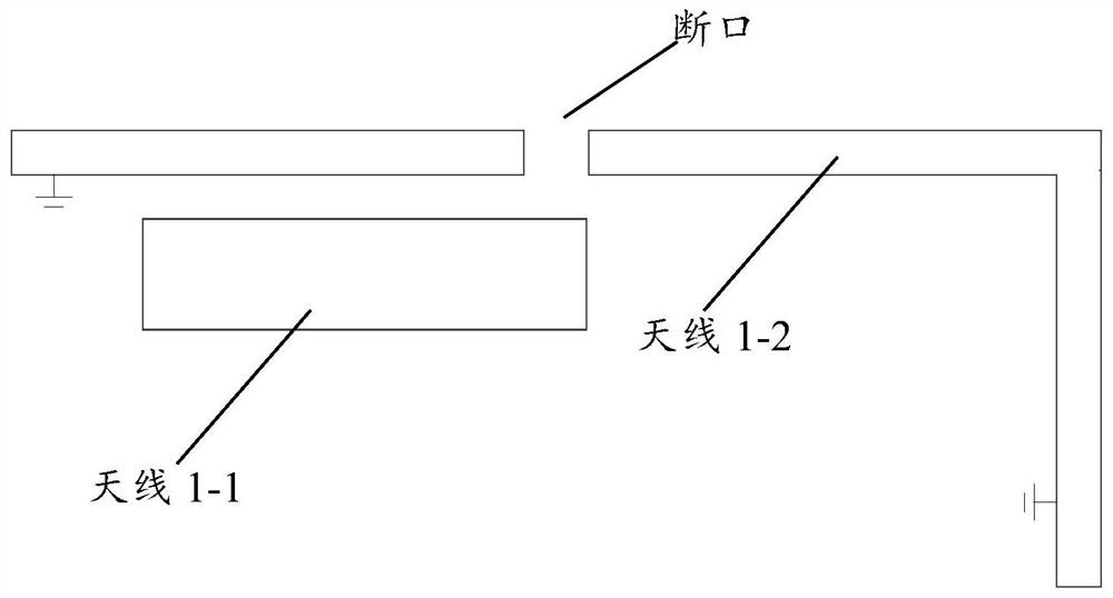
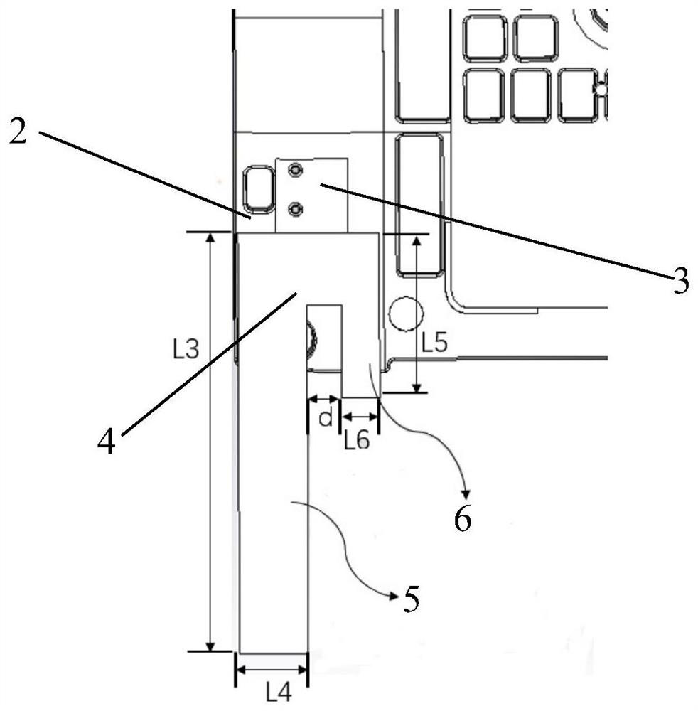
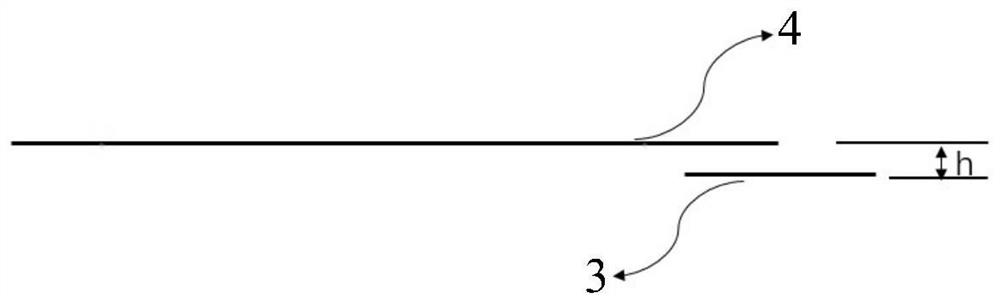
[0021] Such as Figure 2 to Figure 7 As shown in , it is a schematic structural diagram of an electronic device provided by an embodiment of the present invention. The electronic device includes: a housing, the housing includes a non-metallic battery cover 1; a non-conductive support 2, the non-conductive support 2 is located in the housing; an antenna radiation unit, including an excitation antenna unit 3 and a coupling antenna unit 4; wherein the excitation antenna unit 3 is set on the non-conductive support 2, and the coupling antenna unit 4 is set on the non-metallic battery cover; there is a space between the coupling antenna unit 4 and the excitation antenna unit 3, and the excitation antenna unit 3 is in the orthographic projection of the plane wh...


PUM


Abstract

The invention provides an electronic device. The electronic device includes: a housing, the housing includes a non-metallic battery cover; a non-conductive bracket, the non-conductive bracket is located in the housing; an antenna radiation unit, including an exciting antenna unit and a coupling antenna unit; wherein, the The excitation antenna unit is arranged on the non-conductive bracket, and the coupling antenna unit is arranged on the non-metallic battery cover; the coupling antenna unit is coupled and connected with the excitation antenna unit, and the excitation antenna unit is on the A part of the orthographic projection of the plane where the coupling antenna unit is located coincides with the coupling antenna unit. The antenna with the above-mentioned structure in the embodiment of the present invention radiates through the coupling mode without the need for a metal frame fracture to radiate, thereby avoiding affecting the performance of other antennas on the electronic device and the radiation efficiency of its own antenna, thereby improving the performance of the antenna.

Description

technical field [0001] The invention relates to the technical field of communication, in particular to an electronic device. Background technique [0002] At present, the antenna design of electronic equipment has included the Sub-6G frequency band, and there are more and more antennas, and the environment is getting worse and worse. Many Sub-6G antenna designs use Laser-Direct-Structuring (LDS) or Flexible Printed Circuit (FPC), which are made on plastic brackets, but if you want to improve antenna efficiency, LDS or The FPC antenna needs to be close to the outer edge of the terminal or use the fracture of the metal middle frame (made by the metal frame) for radiation. [0003] Such as figure 1 As shown, the existing sub-6G antenna 1-1 is generally close to the metal frame fracture, and there are two main disadvantages: one is that the Sub-6G antenna uses the fracture to radiate, which will affect other antennas at the fracture, such as the efficiency of antenna 1-2, If ...

Claims


Application Information

Patent Timeline
Patent Type & Authority Patents(China)
IPC IPC(8): H01Q1/50H01Q1/36H01Q1/22
CPCH01Q1/22H01Q1/36H01Q1/50
Inventor 田朝玉李日辉刘洋
Owner VIVO MOBILE COMM CO LTD
Why Eureka
Try Eureka