
Hydraulic actuator

An actuator and hydraulic technology, applied in the direction of mechanical equipment, fluid pressure actuation device, fluid pressure actuation system components, etc., can solve the difficulty of control accuracy and response speed, the decrease of EH system reliability, and the expansion of EH system scale, etc. problems, to achieve the effect of reducing the difficulty of equipment investment and operation management, high energy utilization rate, and reducing procurement costs

Active Publication Date: 2014-03-19
SHANGHAI ELECTRIC POWER GENERATION EQUIPMENT CO LTD +1
View PDF10 Cites 9 Cited by
  • Summary
  • Abstract
  • Description
  • Claims
  • Application Information

AI Technical Summary

Problems solved by technology

The seemingly simple idea expands the scale of the EH system, and the oil supply capacity and oil storage capacity of the EH oil supply device need to be recalculated, which objectively increases the burden on the EH system, and the reliability of the EH system decreases with the expansion of the scale
For extraction valves located farther away, this mode is even more unreasonable
If electric or pneumatic actuators are used, the control accuracy and response speed are difficult to meet the requirements of steam turbine control

Method used


Image

  • Hydraulic actuator

Examples


Embodiment Construction

[0043] The implementation of the present invention will be illustrated by specific specific examples below, and those skilled in the art can easily understand other advantages and effects of the present invention from the contents disclosed in this specification.

[0044] see figure 1 . It should be noted that the structures, proportions, sizes, etc. shown in the drawings attached to this specification are only used to match the content disclosed in the specification, for those who are familiar with this technology to understand and read, and are not used to limit the implementation of the present invention. Limiting conditions, so there is no technical substantive meaning, any modification of structure, change of proportional relationship or adjustment of size, without affecting the effect and purpose of the present invention, should still fall within the scope of the present invention. The disclosed technical content must be within the scope covered. At the same time, term...


PUM


Abstract

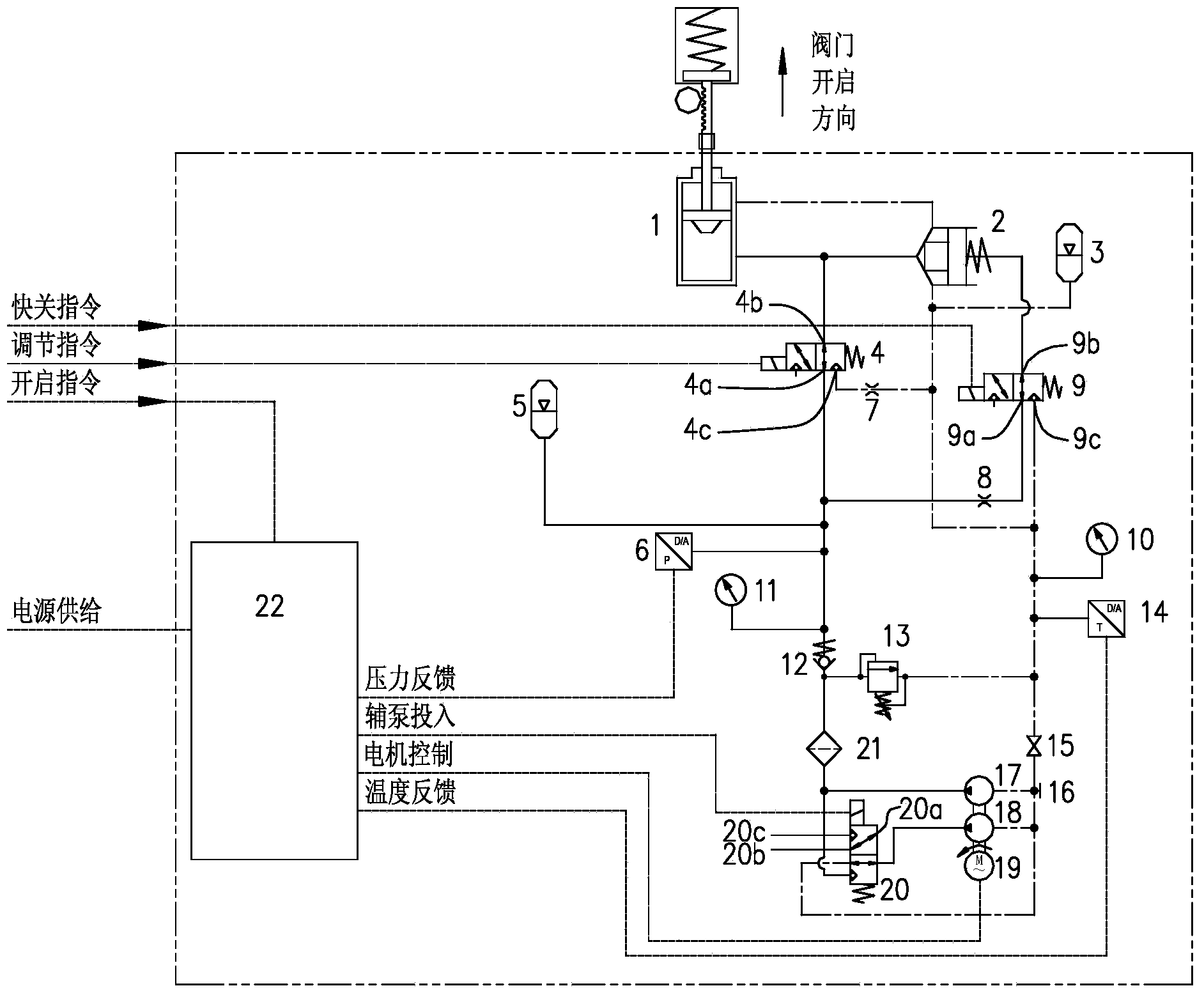
The invention provides a hydraulic actuator. The hydraulic actuator comprises an oil cylinder, a main oil pump, a motor for driving the main oil pump, a high-pressure energy accumulator, an oil-return energy accumulator and a controller, wherein a piston rod of the oil cylinder is connected with an actuation component, and the oil cylinder comprises an oil control cavity and an oil return cavity; an oil outlet of the main oil pump is connected with a liquid inlet of a check valve, a liquid outlet of the check valve is connected with a liquid inlet of a first two-position three-way valve through an oil inlet pipeline, a liquid outlet of the first two-position three-way valve is connected with the oil control cavity, and a liquid return port of the first two-position three-way valve is connected with the oil return cavity; an oil inlet of the main oil pump is connected with the oil return cavity through an oil return pipeline, and an oil suction port and a stop valve are sequentially arranged on the oil return pipeline from the main oil pump to the oil return cavity; a fast valve is connected between the oil control cavity and the oil return cavity; the high-pressure energy accumulator is connected with the oil inlet pipeline, and the oil-return energy accumulator is connected with the oil return pipeline between the stop valve and the oil return cavity; and the motor is connected with the controller. According to the hydraulic actuator, an oil tank is not required to be configured, complicated equipment configurations of hydraulic actuators in the prior art are reduced, and the hydraulic actuator is low in investment and convenient to operate and manage.

Description

technical field [0001] The invention relates to a steam turbine control system, in particular to a hydraulic actuator. Background technique [0002] In the prior art, the steam turbine control system is generally composed of man-machine interface, measuring element, control device, actuator and other parts. The man-machine interface is a variety of operation display devices, such as CRT, various indicator lights / meters, mouse, operation buttons / switches, etc. The measuring elements are various sensors, such as speed measuring heads, thermocouples, transmitters, travel switches, etc., which convert various process variables into different forms of electronic signals and send them to the control device. The control device is the core of the entire control system, and realizes various control functions of the system. The commonly used control devices are all digital control systems based on microprocessor and network technology. Since steam turbines are large-scale high-speed...

Claims


Application Information

Patent Timeline
IPC IPC(8): F15B11/08F15B1/02F15B21/04
Inventor 夏心磊周文龙徐军李节金
Owner SHANGHAI ELECTRIC POWER GENERATION EQUIPMENT CO LTD
Learn More