
A single stage pfc llc circuit

A circuit and single-stage technology, applied in electrical components, adjusting electrical variables, high-efficiency power electronic conversion, etc., can solve the problems of large power frequency ripple and low bandwidth of output voltage

Active Publication Date: 2020-11-13
奇普电源(常州)有限公司
View PDF5 Cites 0 Cited by
  • Summary
  • Abstract
  • Description
  • Claims
  • Application Information

AI Technical Summary

Problems solved by technology

[0006] In this way, in order to realize the function of single-stage PFC, the output feedback loop needs to be much less than twice the power frequency frequency, and the bandwidth is very low. Generally, it is designed to be 10Hz~20Hz, so the power frequency ripple on the output voltage is very large.

Method used


Image

  • A single stage pfc llc circuit
  • A single stage pfc llc circuit
  • A single stage pfc llc circuit

Examples


Embodiment Construction

[0040] The present invention will be further described below in conjunction with the accompanying drawings. The following examples are only used to illustrate the technical solution of the present invention more clearly, but not to limit the protection scope of the present invention.

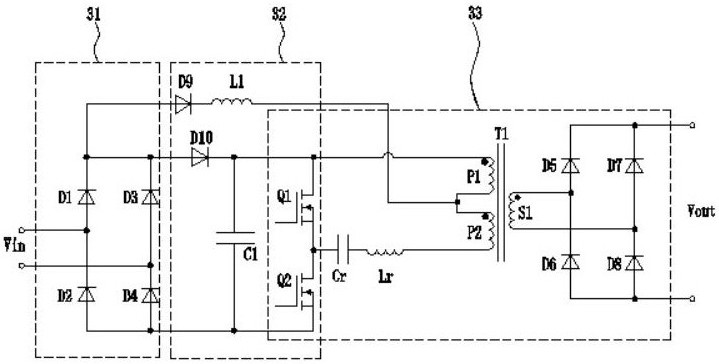
[0041] like image 3 As shown, a single-stage PFC LLC circuit includes: an input rectifier 31, a Boost converter 32 and an isolated DC-DC converter 33; the input rectifier 31 rectifies the input voltage and forms a capacitor C1 in the Boost converter. Charging loop; Boost converter 32 also includes first inductor L1, first switching element Q1 and second switching element Q2; isolated DC-DC converter 33 includes first switching element Q1 and second switching element shared with Boost converter 32 The bridge arm structure of the component Q2, the resonant inductor Lr, the resonant capacitor Cr, the first transformer T1 and the rectification and filtering circuit; the primary winding of the firs...


PUM


Abstract

The invention relates to a single-stage PFC LLC circuit, wherein an input rectifier forms a circuit for charging a capacitor in a Boost converter; the Boost converter also includes a first inductance, a first switching element and a second switching element; an isolated DC-DC The converter includes a bridge arm structure, a resonant inductor, a resonant capacitor, a transformer, and a rectifier filter circuit; one end of the first inductor is connected to the first output end of the input rectifier, and the other end of the first inductor is connected to the middle tap of the primary winding, and connected to The point is connected to the midpoint of the bridge arm structure through a branch including part of the primary winding, resonant inductance and resonant capacitor; or the other end of the first inductance is connected to one end of the primary winding, and the connection point is connected by including a resonant inductance and a resonant capacitor The branch of the circuit is connected with the midpoint of the bridge arm structure, and the other end of the primary winding is connected with the first output end of the input rectifier. In the present invention, the LLC working state of the circuit is not affected, the bandwidth of the output voltage loop can be designed higher, and the power frequency ripple of the output voltage of the secondary side is small.

Description

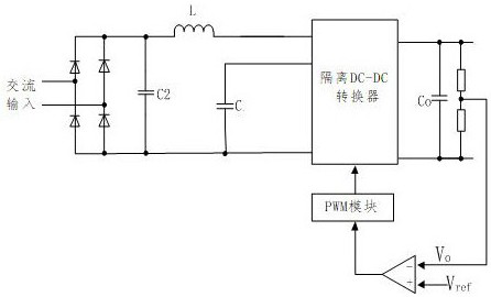
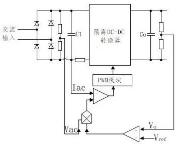
technical field [0001] The invention relates to the technical field of power circuits, in particular to a single-stage PFC LLC circuit. Background technique [0002] The traditional rectifier bridge electrolytic capacitor circuit will seriously distort the input current waveform, the higher harmonic content is relatively high, and the power factor is very low, which greatly increases the load on the power grid. With the promotion of domestic 3C certification, more and more power supplies need to meet certain harmonic requirements in order to pass the certification in the future. In order to meet this requirement, the traditional method is to adopt a two-stage scheme, that is, PFC+DCDC. Although this scheme can achieve relatively high power factor and low harmonic current, it is very expensive. In order to reduce costs, single-stage PFC technology has been paid more and more attention. [0003] In the prior art, such as figure 1 The common way shown is to realize single-st...

Claims


Application Information

Patent Timeline
Patent Type & Authority Patents(China)
IPC IPC(8): H02M7/219H02M3/335H02M1/42
CPCH02M1/42H02M3/33523H02M7/219H02M1/0058Y02B70/10
Inventor 孙巨禄徐明孙涓涓张志成刘建
Owner 奇普电源(常州)有限公司
Learn More