Automated warehouse system
A technology of automatic warehouse and automatic operation, which is applied in the direction of transportation and packaging, storage devices, packaging, etc., and can solve the problems of reduced operating capacity of automatic warehouses
- Summary
- Abstract
- Description
- Claims
- Application Information
AI Technical Summary
Problems solved by technology
Method used
Image

Examples
no. 1 approach
[0048] (1) Overall structure
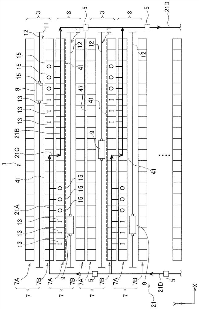
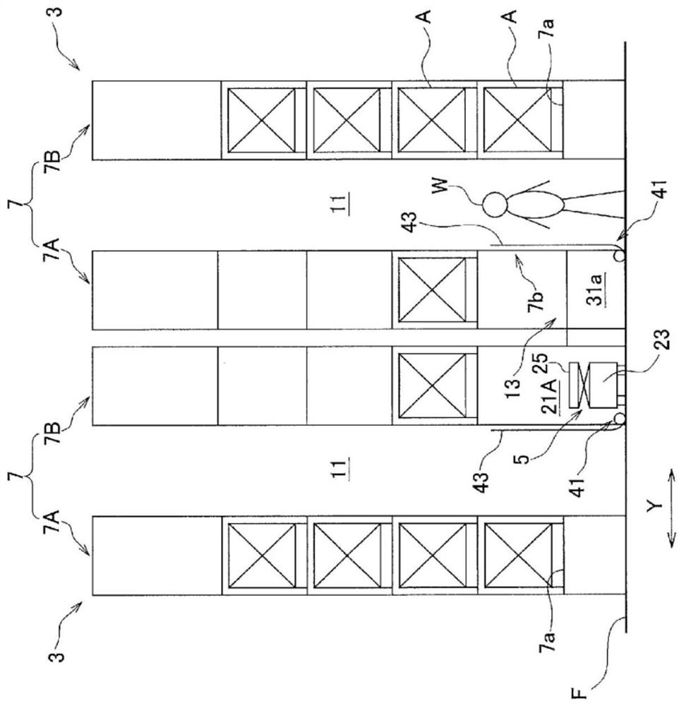
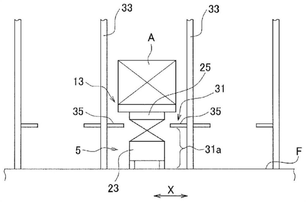
[0049] use Figure 1 ~ Figure 2 The automatic warehouse system 1 according to the first embodiment will be described. figure 1 It is a schematic plan view showing the arrangement structure of the automatic warehouse system according to the first embodiment. figure 2 is a brief main view of the automated warehouse system.
[0050] The automatic warehouse system 1 has a plurality of automatic warehouses 3 and a plurality of transport vehicles 5 .
[0051] Each automatic warehouse 3 has a pair of shelves 7 (first shelf 7A and second shelf 7B) and one stacking crane 9 . The plurality of automated warehouses 3 are arranged such that the rear surfaces of the shelves 7 are adjacent to each other. The transport vehicle 5 carries the article A in and out with respect to the plurality of automatic warehouses 3 .
[0052] In the following, the longitudinal direction of the shelf 7 is the first horizontal direction, indicated by the arrow X. As shown i...
no. 2 approach
[0129] In the first embodiment, one stacking crane 9 is provided in each automatic warehouse 3 , but the number of stacking cranes 9 may be plural.
[0130] use Figure 9 , such a modified example will be described as the second embodiment. Figure 9 It is a schematic plan view showing the arrangement structure of the automatic warehouse system according to the second embodiment. In addition, in the description of this embodiment, the point which differs from 1st Embodiment is demonstrated.
[0131] Such as Figure 9 As shown, in the automatic warehouse system 1A according to the second embodiment, each automatic warehouse 3 has two stacking cranes 9 arranged in series. The route 21 on which the transport vehicle 5 travels includes two first routes 21A, two second routes 21B, and three connecting routes 21C. In the present embodiment, the first route 21A is provided near the other end near one end and the center of the lower portion of the first shelf 7A in the first horiz...
no. 3 approach
[0137] In the first embodiment, the movement restricting device 41 is arranged in the entire area between the crane tunnel 11 and the front surface of the shelf 7 facing the crane tunnel 11 . However, it is sufficient if the movement restricting device 41 is provided in the opening 7 b corresponding to the storage port 13 and the storage port 15 of the rack 7 , and thus is not limited to the first embodiment.
[0138] use Figure 10 , such a modified example will be described as a third embodiment. Figure 10 It is a schematic plan view which shows the arrangement|positioning structure of the automatic warehouse system which concerns on 3rd Embodiment. In addition, in the description of this embodiment, the point which differs from 1st Embodiment is demonstrated.
[0139] The automatic warehouse system 1B has a movement restriction device 41A. The movement restricting device 41A is provided on the side of the crane passage 11 corresponding only to the openings 7b of the sto...
PUM
 Abstract
Description
Claims
Application Information
 - R&D Engineer
- R&D Manager
- IP Professional
- Industry Leading Data Capabilities
- Powerful AI technology
- Patent DNA Extraction
Browse by: Latest US Patents, China's latest patents, Technical Efficacy Thesaurus, Application Domain, Technology Topic.
© 2024 PatSnap. All rights reserved.Legal|Privacy policy|Modern Slavery Act Transparency Statement|Sitemap