Grinding wheel truing method and grinding machine

Inactive Publication Date: 2015-09-17
JTEKT CORP
View PDF4 Cites 9 Cited by
  • Summary
  • Abstract
  • Description
  • Claims
  • Application Information

AI Technical Summary

Benefits of technology

[0009]The present invention has been made in view of such issues, and therefore has an object to provide a grinding wheel truing method and a grindi

Problems solved by technology

Thus, it takes a significantly long time to detect the position of the surface of the grinding wheel, which degrades the efficiency of truing.
In the grinding device described in JP 2009-285776 A, meanwhile, at least one of the wheel spindle

Method used


Image

  • Grinding wheel truing method and grinding machine
  • Grinding wheel truing method and grinding machine
  • Grinding wheel truing method and grinding machine

Examples


Embodiment Construction

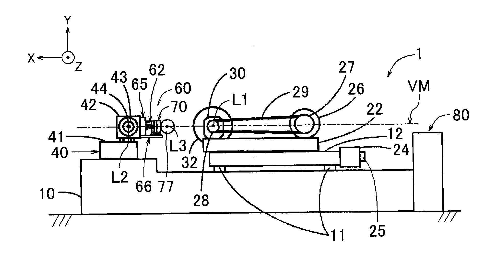
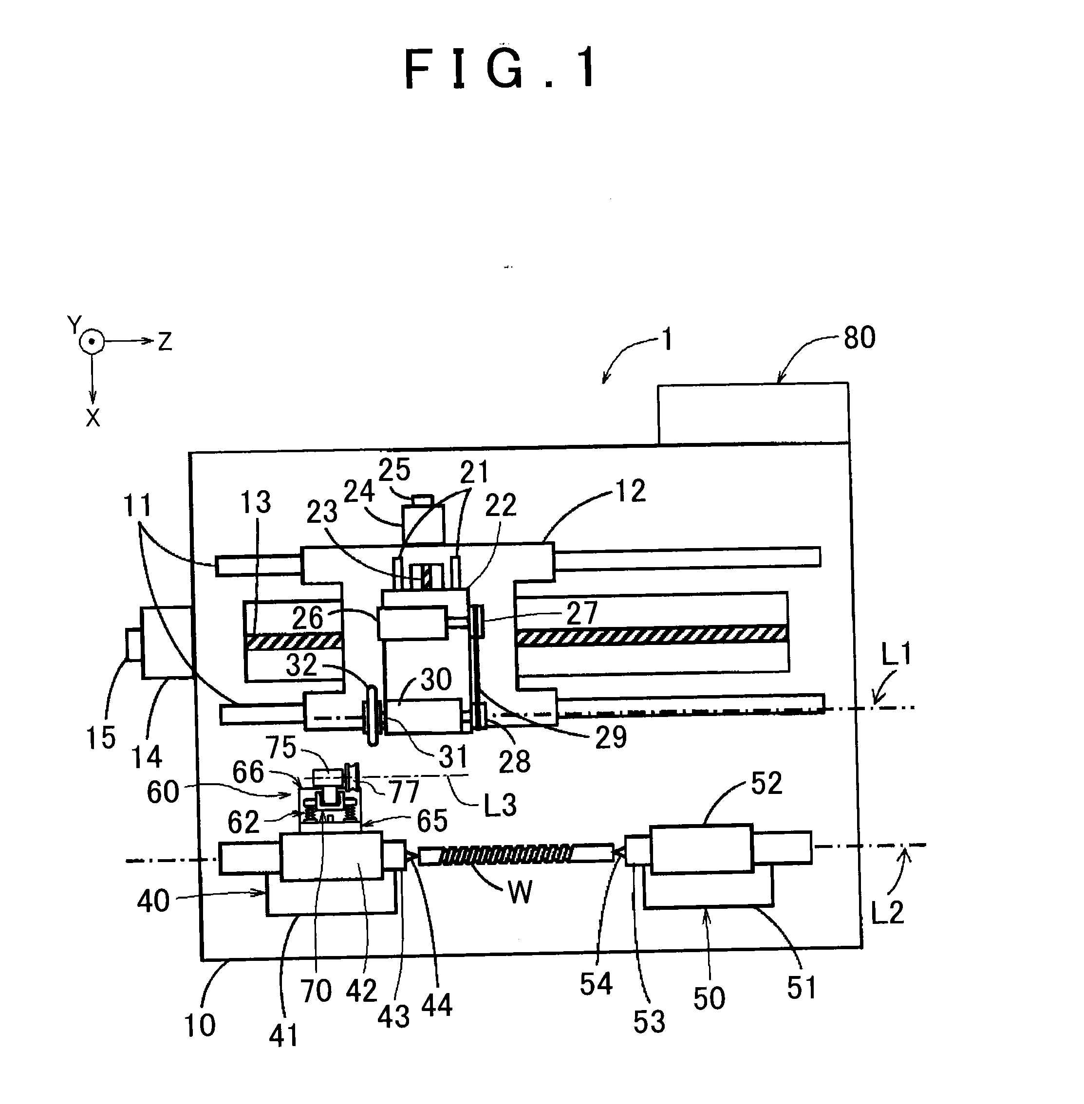
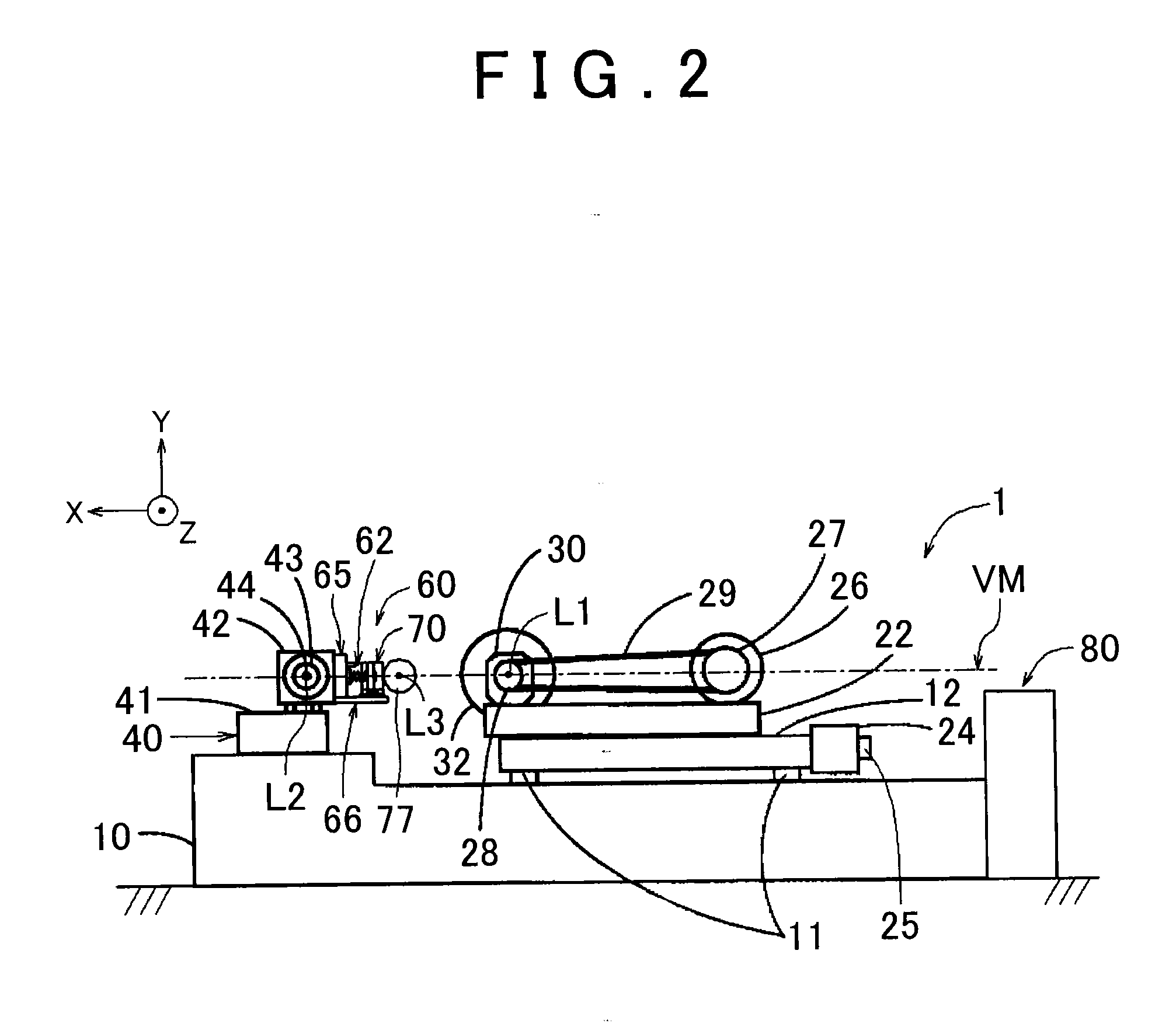
[0029]An embodiment of the present invention will be described below with reference to the drawings. In drawings in which the X axis, the Y axis, and the Z axis are indicated, the X axis, the Y axis, and the Z axis are orthogonal to each other. The Y-axis direction indicates the vertically upward direction. The Z-axis direction indicates a direction that is parallel to a grinding wheel rotational axis L1. The X-axis direction indicates a direction which is orthogonal to the grinding wheel rotational axis L1 and in which a grinding wheel 32 cuts into a workpiece W. The grinding wheel rotational axis L1, a workpiece rotational axis L2, and a truer rotational axis L3 are all parallel to the Z-axis direction.

[0030]FIGS. 1 and 2 illustrate an overall configuration of a grinding machine 1. As illustrated in FIGS. 1 and 2, the grinding machine 1 is configured such that relative movement of the grinding wheel 32 with respect to the workpiece W in the X-axis direction and the Z-axis directio...


PUM

PropertyMeasurementUnit
Shapeaaaaaaaaaa

Abstract

A truing device is supported so as to be elastically movable in the Z-axis direction, which is parallel to a grinding wheel rotational axis, and elastically movable in the X-axis direction in which a grinding wheel cuts into the truing device, and includes a movement restriction device that controls prohibition and permission of elastic movement. The method includes: causing a surface of the grinding wheel to contact the truing device in the X-axis direction; and correcting a shape of the grinding wheel when the grinding wheel cuts into the truing device until the amount of elastic movement of the truing device in the X-axis direction reaches a first predetermined amount, by controlling the movement restriction device to prohibit elastic movement of the truing device, and thereafter causing the grinding wheel to further cut into the truing device in the X-axis direction by a second predetermined amount.

Description

INCORPORATION BY REFERENCE[0001]The disclosure of Japanese Patent Application No. 2014-052927 filed on Mar. 17, 2014 including the specification, drawings and abstract, is incorporated herein by reference in its entirety.BACKGROUND OF THE INVENTION[0002]1. Field of the Invention[0003]The present invention relates to a grinding wheel truing method and a grinding machine.[0004]2. Description of Related Art[0005]In a common grinding machine according to the related art, a truing surface, that is, a surface for reshaping a grinding wheel, of a truer is fixed in position with respect to the grinding machine. Thus, in the case where there is an error in position of a surface to be processed of the grinding wheel in the X-axis direction (a direction in which the grinding wheel cuts into a workpiece and which is orthogonal to the grinding wheel rotational axis) and in position thereof in the Z-axis direction (a direction that is parallel to the grinding wheel rotational axis) due to thermal...

Claims


Application Information

Patent Timeline
IPC IPC(8): B24B53/04
CPCB24B53/04B24B5/04B24B53/062B24B53/14
Inventor ONO, NAOTOOKUBO, SATOSHISAKAI, TOSHIKI
Owner JTEKT CORP
Why Eureka
Try Eureka