Rotary vacuum pump

a vacuum pump and rotary technology, applied in the direction of rotary/oscillating piston pump components, machines/engines, liquid fuel engines, etc., can solve the problems of foreign matter in the clearance, rotors and rotary shafts disposed within the housing are not directly cooled, and rotors and rotary shafts may not return to their original positions

Inactive Publication Date: 2010-06-17
TOYOTA IND CORP
View PDF0 Cites 9 Cited by
  • Summary
  • Abstract
  • Description
  • Claims
  • Application Information

AI Technical Summary

Problems solved by technology

Although the housing is in direct contact with fresh air and therefore cooled easily, the rotors and the rotary shafts disposed within the housing are not directly cooled by fresh air.
Fine particles present in the gas drawn into the pump chamber are easily accumulated in the clearance, thus forming a foreign matter in the clearance.
When the roots pump is stopped and thermally contracted with the foreign matter present in the clearance, the rotors and the rotary shafts may fail to return to their original positions due to the presence of any foreign matter.
When the roots pump is restarted, there is a fear that the roots pump may not be operated properly due to large frictional resistance between the rotor and the foreign matter.

Method used


Image

  • Rotary vacuum pump
  • Rotary vacuum pump
  • Rotary vacuum pump

Examples


Embodiment Construction

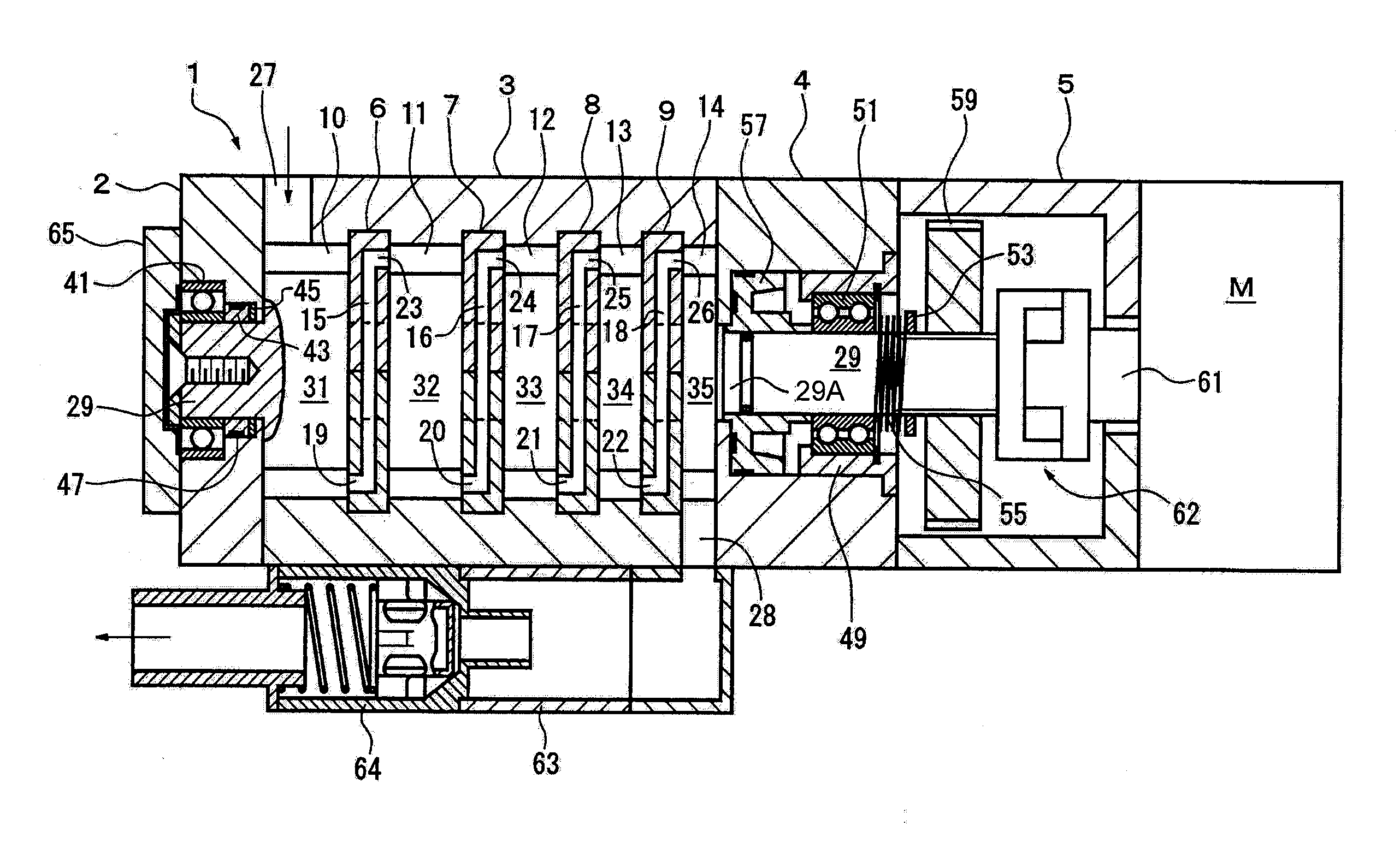
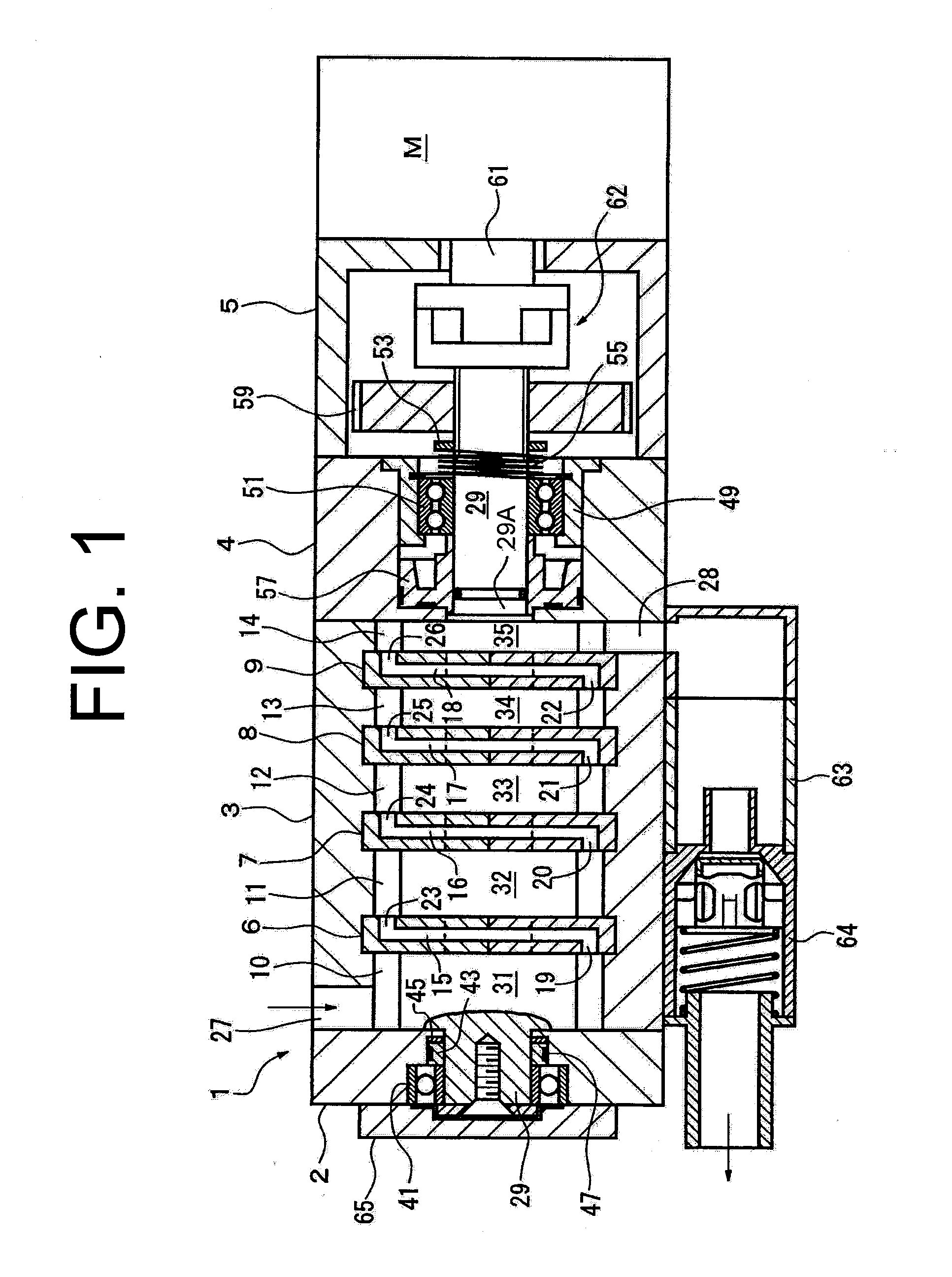
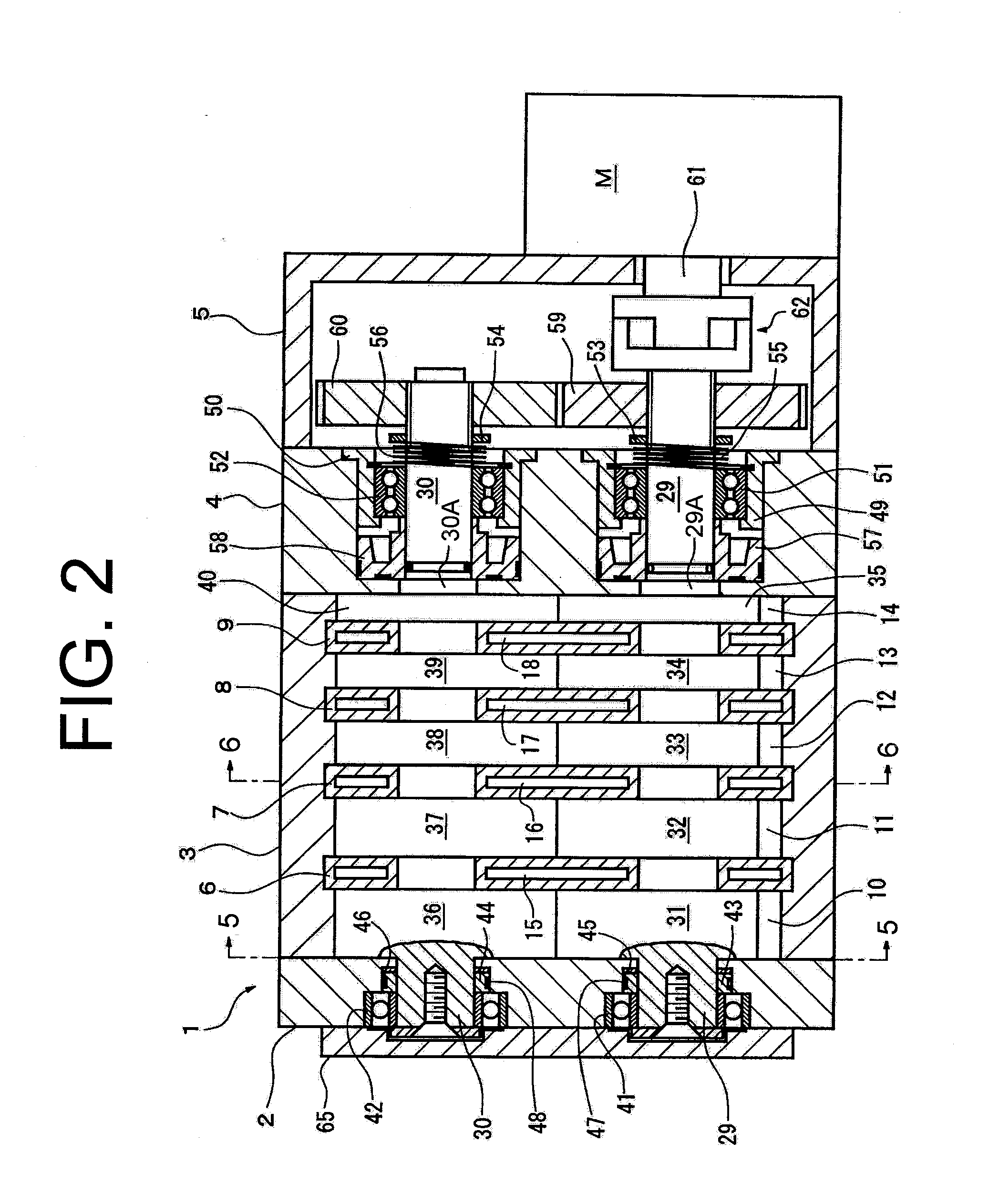
[0021]The following will describe the multistage roots pump according to the first embodiment of the present invention with reference to FIGS. 1 to 6. The multistage roots pump will be referred to merely as roots pump hereinafter. It is noted that the left-hand side and the right-hand side of the roots pump as viewed in FIGS. 1 to 4 correspond to the front and the rear of the roots pump, respectively. It is also noted that the upper side and the lower side of the roots pump as viewed in FIGS. 1 to 4 correspond to the upper side and the lower side of the roots pump, respectively, when installed in place.

[0022]Referring to FIG. 1, the roots pump shown in its longitudinal sectional view has a pump housing indicated generally by reference numeral 1 and including a front housing 2, a rotor housing 3, a rear housing 4 and a gear housing 5 which are joined sealingly together by a plurality of bolts (not shown). As shown in FIGS. 5 and 6, the rotor housing 3 is formed by two upper and lower...


PUM


Abstract

The rotary vacuum pump includes a pump housing, a rotary shaft, a thrust movement restriction mechanism and a first elastic member. The pump housing has therein a pump chamber. The rotary shaft has thereon a rotor rotatably disposed in the pump chamber. When the rotor is rotated with the rotary shaft, gas in the pump chamber is pumped thereby to draw gas into the pump chamber. The thrust movement restriction mechanism is provided for allowing the rotor to displace in the pump chamber in one thrust direction due to thermal expansion thereof during the operation of the rotary vacuum pump. The first elastic member is provided for urging the rotary shaft in the other thrust direction opposite to the one thrust direction.

Description

CROSS REFERENCE TO RELATED APPLICATION[0001]This application claims priority to Japanese Application Nos. 2008-315204 filed Dec. 11, 2008 and 2009-277492 filed Dec. 7, 2009.BACKGROUND OF THE INVENTION[0002]The present invention relates to a rotary vacuum pump having a rotor disposed in a pump chamber and a rotary shaft rotating the rotor for pumping gas in the pump chamber thereby drawing gas into the pump chamber.[0003]Japanese Unexamined Patent Application Publication No. 2008-51116 discloses a multistage roots pump that is a type of rotary vacuum pump. The multistage roots pump of this publication has two parallel rotary shafts disposed in the housing of the roots pump with their opposite ends rotatably supported by radial bearings. Each rotary shaft has thereon a plurality of rotors each disposed in each of a plurality of pump chambers of the housing. The pump chambers are juxtaposed along the axis of the rotary shaft.[0004]Specifically, the rotors of one of the rotary shafts an...

Claims


Application Information

Patent Timeline
Patent Type & Authority Applications(United States)
IPC IPC(8): F04C15/00F04C2/08
CPCF04C18/126F04C29/0021F04C25/02F04C23/001F04C2/14F04C18/18
Inventor YAMAMOTO, SHINYAKOSHIZAKA, RYOSUKEMISHINA, TAKAOSUZUKI, YOSHINARIUCHIYAMA, OSAMU
Owner TOYOTA IND CORP
Why Eureka
Try Eureka