
Method of performing beam failure recovery procedure and user equipment

A technology for user equipment and beams, applied in electrical components, wireless communication, connection management, etc., to solve problems such as PHY and MAC layers that have not yet been determined

Inactive Publication Date: 2020-10-02
NTT DOCOMO INC
View PDF18 Cites 2 Cited by
  • Summary
  • Abstract
  • Description
  • Claims
  • Application Information

AI Technical Summary

Problems solved by technology

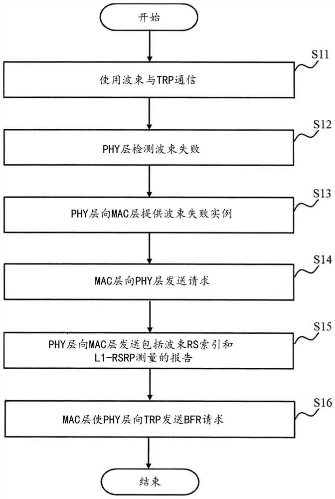
However, in the current NR standard, it has not been determined how the PHY and MAC layers should function during the beam recovery process

Method used


Image

  • Method of performing beam failure recovery procedure and user equipment
  • Method of performing beam failure recovery procedure and user equipment
  • Method of performing beam failure recovery procedure and user equipment

Examples


Embodiment Construction

[0019] Hereinafter, embodiments of the present invention will be described in detail with reference to the drawings. In the embodiments of the present invention, many specific details are explained in order to provide a more thorough understanding of the present invention. However, it is obvious to a person of ordinary skill in the art that the present invention can be practiced without these specific details. In other cases, well-known features have not been described in detail to avoid obscuring the present invention.

[0020] In one or more embodiments of the present invention, the beam may be referred to as a resource or a radio resource.

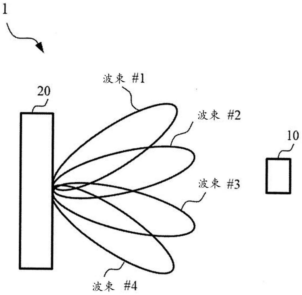
[0021] figure 1 Is a diagram showing an example of the setting of the wireless communication system according to the embodiment of the present invention. Such as figure 1 As shown, the wireless communication system 1 includes a UE 10 and a transmission and reception point (Transmission and Reception Point, TRP) 20. The wireless communicat...


PUM


Abstract

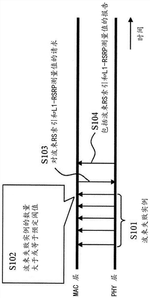
A method of performing a beam failure recovery procedure in a user equipment (UE) that includes a Physical (PHY) layer and a Medium Access Control (MAC) layer includes detecting, with the PHY layer, abeam failure for a beam used for communication between the UE and a base station (BS), receiving, with the MAC layer, one or more beam failure instances from the PHY layer, transmitting, from the MAClayer to the PHY layer, a request for a candidate beam based on a number of the beam failure instances, reporting, from the PHY layer to the MAC layer, first beam information that indicates the candidate beam, and causing, with the MAC layer, the PHY layer to transmit, to the BS, a beam failure recovery request that indicates the candidate beam.

Description

Technical field [0001] One or more embodiments disclosed herein relate to a method for performing a beam failure recovery process in a User Equipment (UE) in a wireless communication system. Background technique [0002] In new radio (NR; fifth-generation (5G) radio access technology) systems that use higher frequencies, beamforming technology becomes critical to achieving adequate coverage and data rates. In the NR system, a user equipment (UE) uses a beam selected in a beam management scheme to communicate with a base station (BS). [0003] For example, when the UE detects a beam failure of the beam used for communication with the BS, the UE performs a beam failure recovery (BFR) procedure. In the BFR process, the physical (Physical, PHY) and Medium Access Control (Medium Access Control, MAC) layers of the UE are required to operate in a coordinated manner. However, in the current NR standard, it has not been determined how the PHY and MAC layers should perform their functions ...

Claims


Application Information

Patent Timeline
Patent Type & Authority Applications(China)
IPC IPC(8): H04W36/30H04W16/28
CPCH04W16/28H04W76/19H04W36/06H04W36/36H04W36/0085H04W36/305
Inventor 柿岛佑一永田聪王静刘敏那崇宁吉冈翔平
Owner NTT DOCOMO INC
Learn More