
Method for controlling measurements in a wireless telecommunications terminal

a technology of telecommunications terminal and measurement procedure, which is applied in the direction of frequency-division multiplex, instruments, high-level techniques, etc., can solve the problems of system inefficiency and system power consumption, and achieve the effect of optimizing the power consumption of an lte u

Active Publication Date: 2011-12-15
INTEL CORP
View PDF5 Cites 21 Cited by
  • Summary
  • Abstract
  • Description
  • Claims
  • Application Information

AI Technical Summary

Benefits of technology

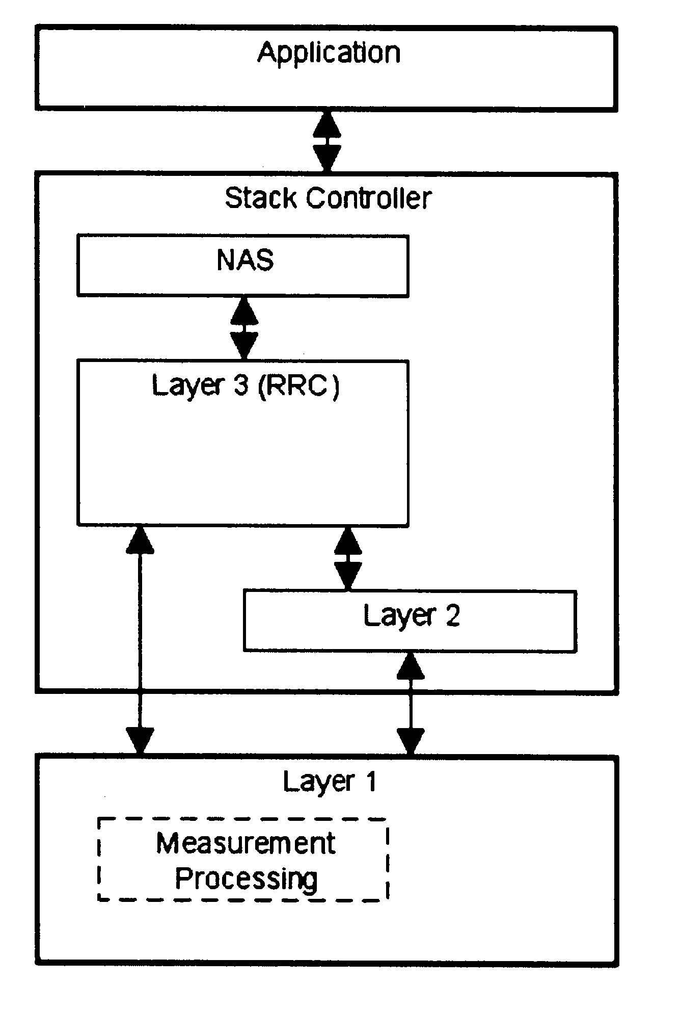
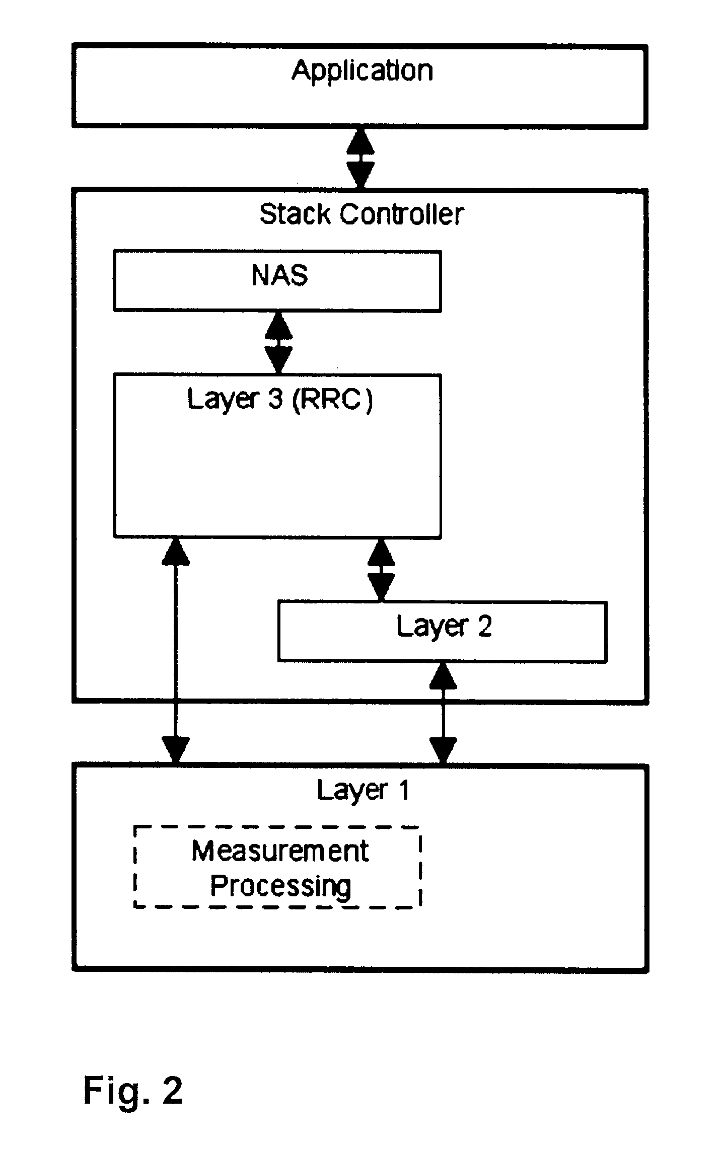
[0009]So in contrast to the distribution of processing tasks as proposed by the LTE standard and implemented in well-known RRC solutions for the measurement functionality, the method according to the invention does a reparation of work split between RRC layer and PHY layer of an LTE UE, thus minimizing the awake time for the RRC layer entity.
[0013]The solution according to the present invention provides a way to optimize power consumption of an LTE UE compared to implementations that follow the standard work split for measurement functionality between RRC and PHY layers where the awake time of the RRC layer entity for performing measurement processing is significantly longer than with the invention.

Problems solved by technology

A continuing major challenge for designers is to reduce the system power consumption of mobile terminals, also known as User Equipment (UE) in LTE terminology.
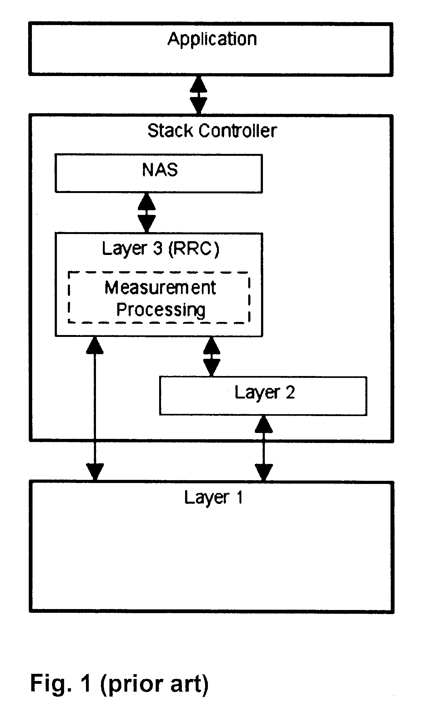
If implemented in the RRC layer as per definition of the standard, some inefficiency with respect to power consumption is system immanent.
The main issue is that the PHY reports every measurement result to the Radio Resource Control (RRC) layer.

Method used


Image

  • Method for controlling measurements in a wireless telecommunications terminal
  • Method for controlling measurements in a wireless telecommunications terminal
  • Method for controlling measurements in a wireless telecommunications terminal

Examples


Embodiment Construction

[0023]FIG. 2 illustrates the basic idea of the invention, namely to re-distribute measurement processing tasks within the protocol stack of a UE such that a major part of measurement processing functionality is assign to the PHY layer (layer 1) instead of the RRC layer.

[0024]For a better understanding, FIG. 3 shows a block diagram of measurement functionality in a UE as required by the LTE standard. Arrow A represents the input of measurements sampled on the radio, i.e. air, interface. The measurements are captured at the physical layer (PHY) where they are subjected to some processing such as averaging, determination of signal power and quality. Arrow B represents the measurement results following PHY processing that are input to a measurement processing block 32 which consists of ‘Layer 3 filtering’ functionality at 321 and evaluation of reporting criteria functionality at 322. The functionality of blocks 321 and 322 is configured by respective parameters that are input to the pro...


PUM


Abstract

A method is provided for controlling measurements in a wireless telecommunications terminal. In a Long Term Evolution (LTE) wireless communication system, the network instructs a UE to measure the received power and quality of the reference signals of the serving cell as well as of neighbor cells. The object of improving the system power consumption of user equipment (UE) that has to perform such measurements is solved by distributing the measurement functionality between RRC and PHY layers such that the RRC layer is enabled to rest in a power save mode unless results of the measurements have to be reported to the network, and to be only active for a minimum to ensure that the UE still behaves standard compliant to the network.

Description

CROSS REFERENCE TO RELATED APPLICATIONS[0001]This application claims priority of European patent application No. 10165671.8 filed on Jun. 11, 2010, the entire contents of which is hereby incorporated by reference herein.FIELD OF THE INVENTION[0002]The invention relates to a method for controlling measurement procedures in a telecommunications terminal affiliated to a wireless telecommunications network.BACKGROUND OF THE INVENTION[0003]3GPP LTE (3rd Generation Partnership Project Long Term Evolution) is the upcoming standard of 4th generation radio access networks. A continuing major challenge for designers is to reduce the system power consumption of mobile terminals, also known as User Equipment (UE) in LTE terminology.[0004]FIG. 1 illustrates a protocol stack of a UE according to LTE standard specifications in the terms of the OSI (Open Systems Interconnection) model of logical layers. As is known in the art, the Non-Access Stratum (NAS) layer protocol is responsible for signallin...

Claims


Application Information

Patent Timeline
Patent Type & Authority Applications(United States)
IPC IPC(8): H04W52/02H04W72/54
CPCH04W24/10H04W72/0406Y02B60/50H04W52/0225H04W72/085H04W52/0232H04W52/02H04W52/0229H04W52/0264H04W52/0261H04W52/0241H04W52/0222H04W52/0209H04W52/0245H04W52/0274H04W52/028Y02D30/70H04W72/542H04W72/20H04L43/02H04L43/067H04L43/04H04L43/0817H04L43/022H04L43/0811H04L43/06H04L43/024
Inventor HOFMANN, MATTHIASKONRAD, THOMAS
Owner INTEL CORP
Learn More