Optical/electric interface module space multiplexing method and apparatus used for Ethernet SFP interface

A space multiplexing, Ethernet technology, applied in electrical components, data exchange through path configuration, transmission systems, etc., can solve problems such as the inability to provide SFP electrical interface solutions

Inactive Publication Date: 2005-09-28
黄炜
View PDF0 Cites 22 Cited by
  • Summary
  • Abstract
  • Description
  • Claims
  • Application Information

AI Technical Summary

Problems solved by technology

The defects of the above solutions mainly include: 1) cannot provide 10 / 100BASE-T SFP electrical interface solution; 2) cannot provide 10 / 100 / 1000BASE-T SFP electrical interface solution

Method used


Image

  • Optical/electric interface module space multiplexing method and apparatus used for Ethernet SFP interface
  • Optical/electric interface module space multiplexing method and apparatus used for Ethernet SFP interface
  • Optical/electric interface module space multiplexing method and apparatus used for Ethernet SFP interface

Examples


Embodiment 1

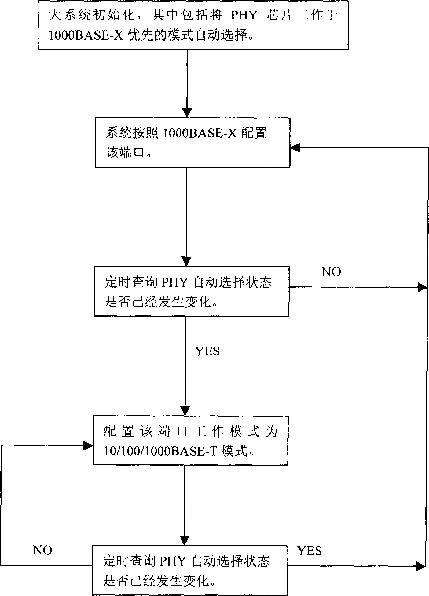
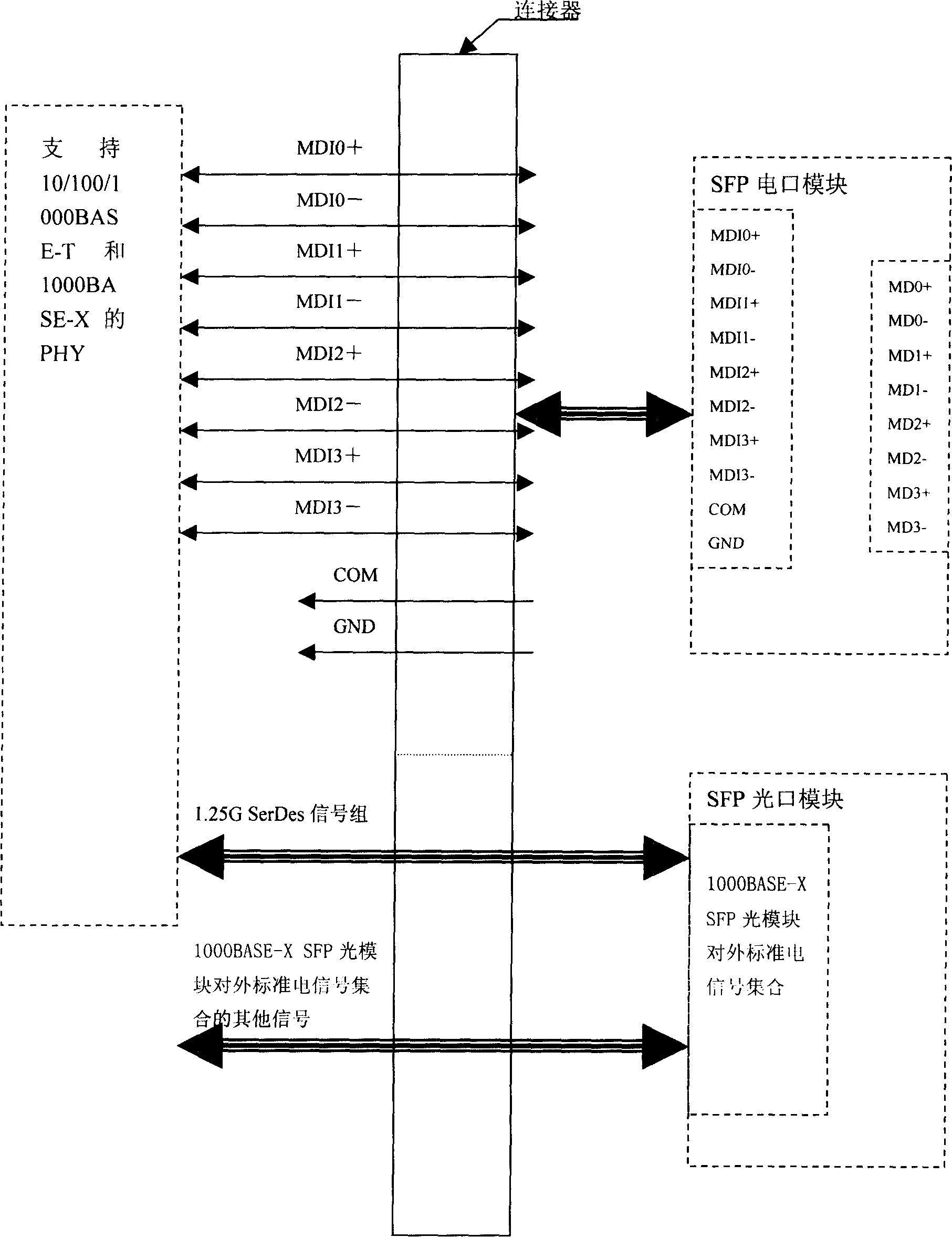
[0011] Embodiment 1: Take the photoelectric multiplexing of a single Gigabit Ethernet SFP interface as an example. In this embodiment, a physical layer chip that supports both 10 / 100 / 1000BASE-T electrical port mode and 1000BASE-X optical port mode is used, and supports Two modes of automatic selection function, the PHY chip can work in the preferred 10 / 100 / 1000BASE-T mode or the preferred 1000BASE-X mode, or the mode in which the negotiation was successful first or the previous negotiation was successful. The flow chart of this embodiment is set to the automatic selection mode that gives priority to 1000BASE-X. circuit reference image 3 , consists of a PHY unit circuit and the multiplexing device (that is, the special connector). In actual use, users can insert SFP electrical port modules or SFP optical port modules into the SFP CAGE according to needs. The following is a detailed introduction to the multiplexing method flow and multiplexing device that constitute this paten...

Embodiment 2

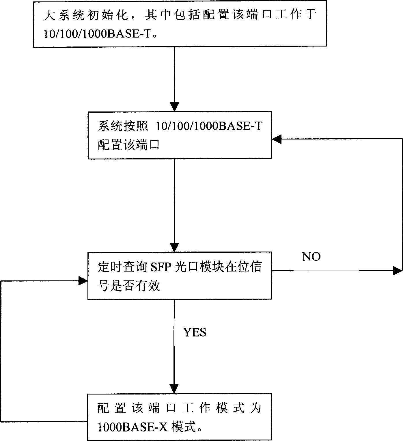
[0014] Embodiment 2: Take the photoelectric multiplexing of a single Gigabit Ethernet SFP interface as an example. In this embodiment, a physical layer chip that supports both 10 / 100 / 1000BASE-T electrical port mode and 1000BASE-X optical port mode is used. Large system This port can be configured to work in 10 / 100 / 1000BASE-T mode or 1000BASE-X mode by default, and the in-position signal can be identified by timing query or interrupt. This flow chart takes the default 10 / 100 / 1000BASE-T mode and the method of regularly checking whether the optical module is in place as an example. The circuit reference image 3 (see the introduction of embodiment 1 for details). The following is a detailed introduction to the process of the multiplexing method that constitutes this patent:

[0015] 1) When the large system is initialized, configure the port to work in 10 / 100 / 1000BASE-T mode. If users need to use this mode for networking, they can directly insert the 10 / 100 / 1000BASE-T SFP electr...


PUM


Abstract

The present invention relates to the field of Ethernet exchange equipment and router equipment, mainly, it is an optical / electric interface module space multiplexing method for Ethernet SFP interface and its device. Said method includes: 1). adopting PHY chip for supporting 10 / 100 / 1000 BASE-T and 1000 BASE-X function; 2). interface of 10 / 100 / 1000 BASE-T adopts special SFP electric interface module; 3). 1000 BASE-X adopts general SFP kilomega optical interface module; 4). at SFP interface side of PHY chip using multiplexer equipment provided by said invention for supporting SFP electric module and SFP optical module and making space multiplex in same SFP CAGE space; 5). according to the detected result large system can make correspondent configuration for said port so as to make said port be worked in electric interface or optical interface module.

Description

technical field [0001] The present invention relates to the field of Ethernet switching equipment and router equipment, and mainly relates to a space multiplexing method and device for an optical / electrical interface module of an Ethernet SFP interface. In order to facilitate users to flexibly select a 10 / 100 / 1000BASE-T interface module or Space multiplexing technology of 1000BASE-X interface module. Background technique [0002] In the current Ethernet SFP (Small Form_Factor Pluggable) port solution, only 1) 100BASE-X SFP module optical interface; 2) 1000BASE-X SFP module optical interface; 3) 1000BASE -T SFP module electrical interface. The defects of the above solution mainly include: 1) the SFP electrical interface solution of 10 / 100BASE-T cannot be provided; 2) the SFP electrical interface solution of 10 / 100 / 1000BASE-T cannot be provided. At present, with the increase in the density of optical interfaces and the popularization of mixed use of optical / electrical interf...

Claims


Application Information

Patent Timeline
IPC IPC(8): H04L12/28H04L29/02
Inventor 黄炜
Owner 黄炜
Why Eureka
Try Eureka